
Process Control Philosophy
The most critical part of process plant design — and the one document where safety, operability and economics are forced to agree. This is an interactive walk-through: move the sliders, flip the permissives, and watch the reconciliation happen. Nitric acid and an exothermic batch are used only as worked examples; the logic transfers to any plant.
Where three arguments are forced to agree
Most projects treat the control philosophy as a deliverable to close before DCS configuration starts. It is more usefully understood as the document where three otherwise separate arguments are made to reconcile.

What is the process allowed to do before protection intervenes? What can an operator reasonably be asked to manage at three in the morning? And what must the plant achieve commercially to justify having been built? Every control loop sits at that intersection whether or not anyone writes it down. The philosophy is simply the decision to write it down before commissioning discovers it for you.
Written that way, the setpoint is not a number handed down by the licensor. It is a negotiated position — and the control philosophy is the record of the negotiation.
What the document is actually securing
A control philosophy secures four things, and projects routinely deliver documents that secure only the first.

The engineer who understood why a condensate-pot level carries a low-low interlock stopping the pump — rather than an alarm — is not the engineer commissioning it. Intent that lives only in a P&ID and a loop list does not survive the transfer.
The load-bearing function. A BPCS keeps the plant on target; an SIS puts it in a safe state when the BPCS has failed to. Blur the two and independence is quietly lost — and the LOPA on paper stops describing the plant that exists.
Individually elegant schemes can be collectively unintelligible. A split range where valve A opens before valve B, shown as two independent positions with no indication of the split, will be fought during the first upset.
Turndown, product concentration, energy integration, catalyst life — these live or die in the control layer. A plant designed for 62 % acid that cannot hold concentration through ambient swings does not earn what the feasibility study promised.
Continuous plants — choosing the controlled variable
The first decision is not how to control. It is what to control — which single variable stands in for plant performance, and what everything else becomes subordinate to.
Return to nitric acid. Capacity is set by the reaction of ammonia and air over a platinum gauze. Three candidates present themselves for the primary manipulated variable — and each of the three drivers rules one of them in or out.
Air is free, it is the bulk stream, it is what the turbotrain compresses. The whole energy balance hangs off the air side. Plant rate is expressed as an air rate.
Set ammonia independently of air and any air disturbance — a trip, a guide-vane move, an ambient shift — walks the mixture toward the flammable region unasked. Unacceptable, however well tuned.
Complexity then argues the ratio is still the wrong thing to hand the operator — it is a means, not an end. What actually determines conversion, platinum loss, gauze life and both trip limits is gauze temperature. So temperature becomes the master, the ratio controller its slave, and the operator enters a temperature (~890 °C) while the system works out the ratio that delivers it.
Batch plants — criticality sets the parameter and the margin
For a batch or semi-batch reaction the same question — what do we control — has a different answer, dictated by thermal criticality rather than throughput economics.
Stössel’s framework compares four temperatures: the process temperature Tp, the maximum temperature of the synthesis reaction MTSR reached adiabatically if all accumulated reactant converts, the technical limit Ttech (boiling point or MAWP-equivalent), and TD24, where time-to-maximum-rate under adiabatic conditions falls to 24 hours. Where those four sit relative to one another places the reaction in one of five classes — and the class decides whether temperature can be the controlled variable at all.
Jacket temperature control with a temperature master is adequate. The adiabatic excursion is contained by the technical limit; control failure is unpleasant, not dangerous.
Two batches at identical temperature can carry entirely different unreacted feed. The controlled parameter shifts to dosing rate, and dosing becomes conditional rather than continuous.
Permissives — the working control layer of a class-4 batch
The practical architecture is a set of conditions under which dosing is allowed to proceed, and the absence of any one of which stops it. Toggle them.
Note the last permissive. If the jacket has stopped taking out heat while feed continues, the reaction has stalled, feed is accumulating, and continuing to dose is the single most dangerous thing the plant can do. Where accumulation is inferred rather than measured, that inference belongs in the control system — and the philosophy is where it is justified.
The dump and the quench
A class-4 reaction needs a defined action for the case where cooling is genuinely lost with feed accumulated. There are two credible ones, and choosing between them is real engineering.
Route the batch under gravity or N₂ pressure into a receiver pre-charged with cold diluent, the mass ratio chosen so the combined system settles below the technical limit. Removes the mass from the heat source — but needs a large, always-empty receiver and a line that cannot plug.
Add cold diluent or a chemical stopper directly to the reactor. Faster and simpler — but adds volume to a vessel that may lack freeboard, and cold shock into a hot exothermic mass has its own consequences.
This is also where the batch document diverges structurally from the continuous one. There is no steady state to defend — the controlled variable is a trajectory: a ramp, a hold, a dosing profile, an endpoint. ISA-88’s vocabulary of procedures, operations and phases is worth adopting even without a formal batch engine, because it prevents the commonest batch failure: a sequence fully specified going forward and entirely unspecified going backward.
The instrumentation layer — and how much of it belongs here
There is a persistent confusion between a control philosophy and a set of loop narratives. A useful test: if removing every tag number destroys the document’s meaning, it is a loop narrative wearing the wrong title.
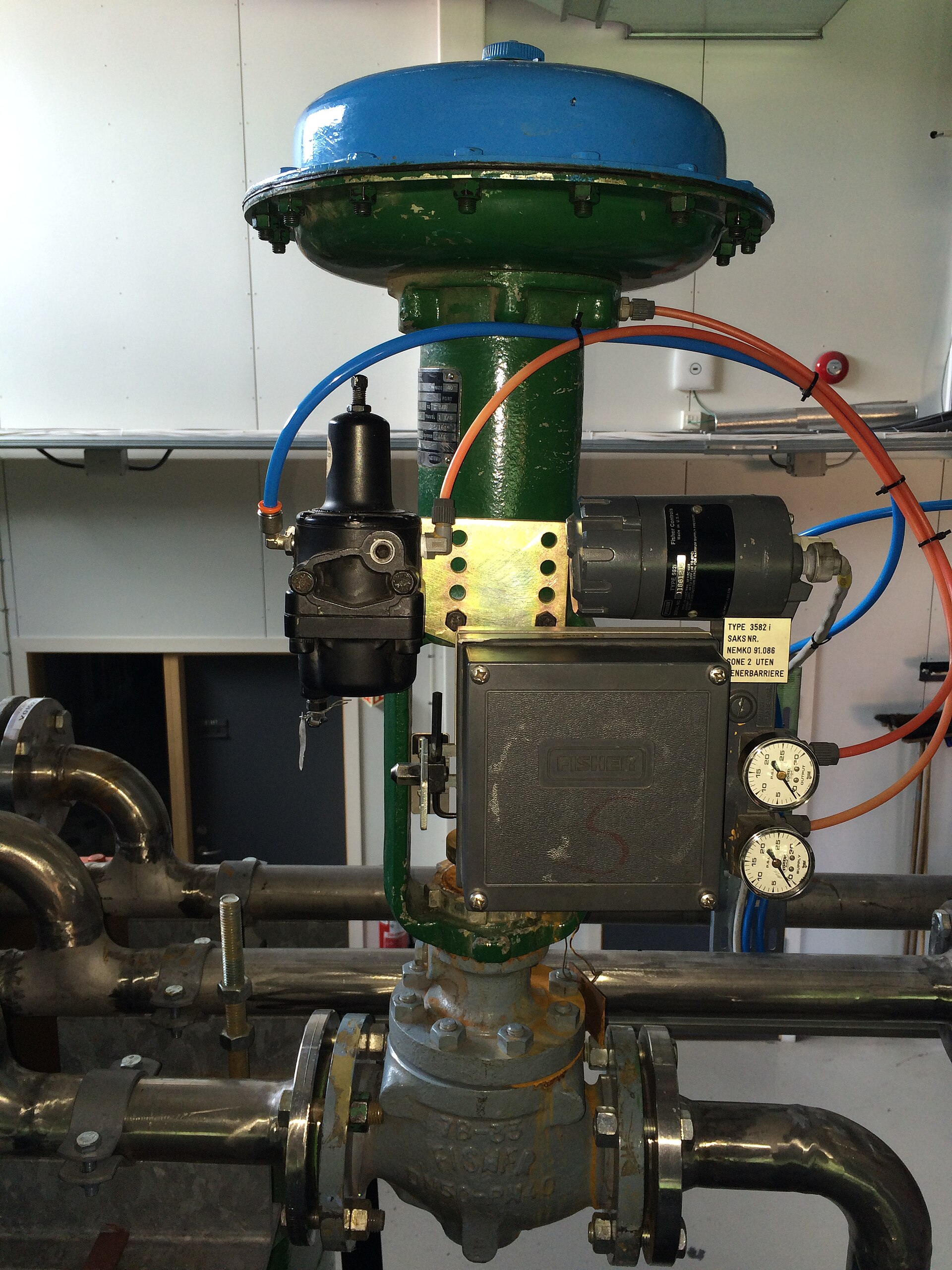
The narrative answers what is measured, in what units, into what block, with what tuning and alarm limits. The philosophy answers why this variable is controlled, what it is a proxy for, what governs it during a transient, and who has authority over it. What the philosophy must state about instrumentation is limited but non-negotiable.
Acid concentration from density & temperature is a regression valid only over its fitted range. Accumulation from jacket duty is a proxy. The failure mode of an inference is not the failure mode of a measurement — so say where control acts on one.
Orifice/venturi flow is a ΔP inference calibrated at design density; off-design it drifts. For a safety-critical ratio, that drift is a safety error, not an accuracy error. T&P compensation is mandatory on both sides.
A valve that fails closed is not automatically safe — a cooling-water valve failing closed on a class-4 reactor is a hazard, not a protection. Reconcile the valve engineer’s fail-safe with the control scheme explicitly.
Trips that can’t arm at start-up must be bypassed — and the bypass must expire without anyone remembering. Arm after normal temperature holds five minutes; re-bypass one minute after a trip so the next start-up is possible.
BPCS — keep on target
- Ratio from T&P-compensated flows
- Tuned for accuracy
- Operator-adjustable within limits
SIS — put in a safe state
- Separate transmitters
- Independent ratio computation
- Conservative selection biases the trip safe
That the protection-side calculation should deliberately differ — selecting the higher of redundant fuel readings and the lower of redundant air readings, so instrument error always moves the trip in the safe direction — is a philosophy decision, invisible on a P&ID, and precisely the sort of thing lost when the document is written as a loop list.
Master, slave & cascade — selecting and implementing
Cascade is the most commonly specified and least commonly justified structure in process plants. It earns its place under one condition.
Cascade is an authority structure — the part most often omitted and the part that matters most. Placing the ratio controller in slave with a hard setpoint high-limit means the operator can ask for more temperature but cannot ask for a ratio the safety case forbids. The plant is safe not because the operator is careful but because the architecture does not offer the unsafe option. Reducing the number of ways a competent person acting reasonably can reach a bad outcome is the practical content of designing for operability.
For each controller: which of manual / auto / cascade are permitted, and when. A slave whose manual is enabled only during commissioning; a master permitted in auto but never cascade because nothing sits above it. Enforce in configuration, not by instruction.
Three mechanisms belong in the document: bumpless transfer, so switching modes doesn’t step the valve; back-initialization, so a master tracks its slave’s real setpoint; and anti-windup bounded by the slave’s actual range.
Split range and fan-out encode economics. When one controller drives two valves — a cheap preferred source and an expensive fallback — the split point, overlap and sequencing express a commercial preference: condensate before demineralised water; turbine extraction before letdown; ammonia-water to the auxiliary superheater before export. Those preferences save real money every hour and are invisible on a P&ID, which makes the philosophy the only place they survive. And ratio is not cascade — a ratio maintains a proportion, it does not receive a setpoint in its own units; confusing the two produces schemes that cannot physically obey.
Finalizing — the five questions that fix a philosophy
A control philosophy is not finalized by being issued. It is finalized by being made to correspond to a plant that exists. Where a document is in circulation and its adequacy is in doubt, test it against these — and repair whatever fails.
For every major loop, can someone state which of economics, safety or operability drove the choice? If the only answer is “the licensor specified it,” the philosophy is a transcription and the negotiation never happened.
For reactive systems: is there a criticality class supported by calorimetry, and does dosing rate follow from a stated accumulation limit? An assumed margin is a permanent, usually invisible tax on capacity.
Trace each safety-critical variable: measured twice, computed twice, and not defeatable by a mode change. Confirm no protective action depends on a controller the operator may put in manual.
Start-up, shutdown, trip recovery, feed changeover, batch abort. Most philosophies describe the steady state well and the transitions badly — and every transition is where commissioning spends its time.
This one requires actually checking. Divergence between document and system is the normal condition of a plant a few years past handover — and it is how a system quietly stops being the system that was analysed.
Freeze the most critical control logic of your plant
The control philosophy is where safety, operability and economics are forced to agree — and where an assumed margin or a blurred BPCS/SIS boundary quietly costs you capacity or safety for the life of the plant. If you need help freezing (finalizing) your control philosophy, or you want an independent validation of one already in circulation, a short conversation usually saves a great deal of commissioning time and capital.
Let’s freeze your control logic
Tell me a little about your process — I help teams finalize control philosophies and independently validate the control/protection boundary, criticality margins and cascade architecture for chemical plants.
Your details are sent directly to me and treated in confidence.