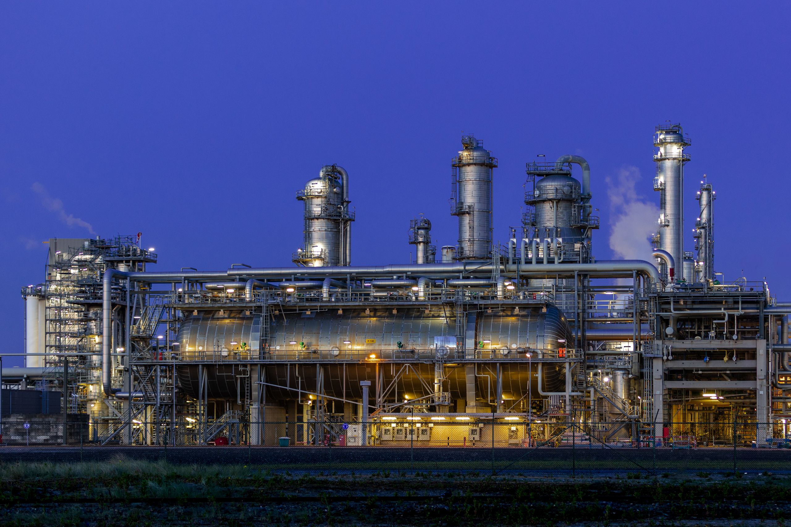
Almost every conversation about hydrogen today is really a conversation about syngas. Green, blue, grey, coal-derived, LNG-derived, biomethane-derived — the feedstocks and the politics differ enormously, but a very large share of the world’s industrial hydrogen still arrives through one common conceptual step: converting a hydrocarbon-rich gas into a controlled mixture of hydrogen and carbon oxides. This article is about how that step actually works, and about the engineering decisions a process engineer has to make before the syngas ever reaches the shift section.
About the numbers in this article. Every figure quoted here is a publicly published, industry-typical range or a clearly stated illustrative calculation. Nothing in this article reproduces any specific plant’s design data, any licensor’s proprietary scheme, or any confidential operating parameter. Values are tagged TYPICAL RANGE where they represent open-literature industry practice and ILLUSTRATIVE where they come from a worked example built on stated assumptions. The purpose is to let you understand a reformer — not to let you redesign one.
- The hydrogen revolution is a syngas revolution
- Scope: where this article starts and stops
- What is really entering the reformer?
- Feed composition drives pretreatment
- The generic block flow
- SMR versus ATR
- The downstream product defines the syngas
- The first engineering decision: pressure
- Joule–Thomson cooling and hydrates
- Compressor configuration
- Inside the primary reformer
- Reforming reaction chemistry
- Kinetics versus equilibrium
- Why firing is required
- The heat balance is an economic story
- What the operator is actually controlling
- How configuration changes with application
- Worked numerical examples
- Oversimplifications to avoid
- Self-check and further reading
1. The hydrogen revolution is actually a syngas revolution
Pick up any industry publication and you will find hydrogen sorted by colour. Green hydrogen from electrolysis. Blue hydrogen from natural gas with carbon capture. Grey hydrogen from natural gas without it. Alongside these sit coal-to-methanol, coal-to-ammonia, LNG-based hydrogen, and the growing interest in compressed biogas and biomethane as feedstocks.
These pathways look completely different at the front end. A coal gasifier and an electrolyser have essentially nothing in common. But look at what the downstream chemistry actually needs, and a pattern appears. Ammonia synthesis needs hydrogen and nitrogen in a particular ratio. Methanol synthesis needs hydrogen, carbon monoxide and carbon dioxide in a particular ratio. Fischer–Tropsch needs hydrogen and carbon monoxide in a particular ratio. Refinery hydrotreating needs hydrogen of a particular purity and pressure.
In every one of those cases except pure electrolysis, the plant is not really in the business of making hydrogen. It is in the business of making a synthesis gas of specified composition. Hydrogen is one component of that gas. The reformer — or the gasifier, or the autothermal reactor — is the unit that turns a carbon-and-hydrogen-bearing feed into that specified composition.
The framing that matters: a reformer is not a hydrogen generator that happens to make some CO. It is a composition-setting unit operation. Everything you will read about temperature, pressure, steam ratio and catalyst is ultimately about hitting a composition target at an acceptable cost.
2. What this article covers — and what it does not
The scope is deliberately narrow, because the alternative is a survey that teaches nothing well.
In scope
Methane-rich gaseous feed → feed conditioning and pressure control → contaminant removal → steam addition → preheat → reforming → syngas leaving the reforming section, up to the inlet of the water-gas shift system.
Out of scope
Shift reactor design, PSA and adsorption cycles, CO2 capture and removal systems, methanation, ammonia synthesis loops, methanol synthesis loops, and hydrogen purification. These appear only where they explain why the reformer outlet composition matters.
Solid feeds are also out of scope. Coal and biomass gasification produce syngas by a different route with different contaminants and a different front end; the reforming chemistry discussed here begins with a gas that is already predominantly methane.
3. What is really entering the reformer?
Define the boundary first. This article assumes a gaseous feed in which methane is roughly 85–95 mol% or higher TYPICAL RANGE, with the balance made up of heavier hydrocarbons, carbon dioxide, nitrogen, hydrogen, sulfur species, water and traces of other contaminants.
That gas may have come from a transmission pipeline, from LNG regasification, from compressed biogas or upgraded biomethane, from associated gas at an oil field, from coal-bed methane, or from a refinery off-gas stream. Here is the point that beginners consistently miss:
The origin of the methane matters far less than the analysis of the gas. A reformer does not know whether its carbon came from a gas field or a digester. It responds to the mole fractions, the sulfur speciation, the heavier-hydrocarbon content and the pressure and temperature at its battery limit. Two feeds from completely different sources with the same analysis will behave the same way; two feeds from the same source with different analyses will not.
What differs by source is the likelihood and variability of particular contaminants. Biomethane is more likely to carry siloxanes, oxygen and variable CO2. Associated gas is more likely to carry heavy ends. Odorised pipeline gas carries deliberately added sulfur compounds. Design for the analysis; use the origin to decide how much margin and how much analytical vigilance you need.
The components, one at a time
Methane and the light hydrocarbons (CH4, C2H6, C3H8, C4+)
Methane is the design case, but the heavier hydrocarbons are the ones that cause trouble out of proportion to their concentration. Three effects matter.
They crack more easily. Higher hydrocarbons dissociate on a nickel surface at lower temperatures than methane does. If they reach hot catalyst without enough steam present, they can lay down carbon before they have a chance to reform. This is why the front end of a reformer tube — the region where the gas is heating up but the reaction has not yet consumed the heavy ends — is a classic carbon-formation zone.
They change the heat duty. Reforming a mole of ethane or propane consumes considerably more heat than reforming a mole of methane, and produces more moles of product. A feed that drifts heavier raises the endothermic load on the tubes at constant molar throughput.
They change the steam requirement. Carbon-formation resistance depends on steam per atom of carbon, not steam per mole of feed. A heavier feed carries more carbon atoms per mole, so the same volumetric steam addition gives a lower effective steam-to-carbon ratio.
The practical consequences chain together: heavier feed → more carbon per mole → higher steam demand and higher duty → hotter tube wall for the same conversion → shorter tube life and higher carbon risk. Where a feed regularly contains significant C2+, designers commonly place an adiabatic pre-reforming step upstream of the fired reformer to convert the heavy ends to methane, CO, CO2 and H2 at moderate temperature before the gas ever sees the radiant tubes.
Sulfur compounds — the classic poison
Sulfur reaches a reformer as hydrogen sulfide, as mercaptans, as carbonyl sulfide, as carbon disulfide, as thiophenes, and as whatever odorant the distribution utility injects. It matters more than almost anything else in the analysis because nickel reforming catalyst is poisoned by sulfur through chemisorption on the active metal surface.
The chain of consequences is worth memorising, because it is the same chain in every plant:
Note that the first visible symptom is usually not a composition change. It is a thermal symptom: hot bands on the tubes, or a rising tube skin temperature at constant firing. The reaction absorbs heat; where the reaction stops, the heat has nowhere to go except into the metal.
Total sulfur versus speciation. A single total-sulfur number is not enough for design. Hydrogen sulfide is removed readily by a zinc oxide absorbent. Organic sulfur species generally are not — they must first be converted to H2S over a hydrogenation catalyst, which requires hydrogen to be present in the feed and a suitable inlet temperature. A feed whose sulfur is mostly mercaptan needs a fundamentally different pretreatment train from one whose sulfur is mostly H2S, even at identical total sulfur.
Typical requirements at the reforming catalyst inlet are in the region of a small fraction of a part per million of total sulfur TYPICAL RANGE, which is why the pretreatment section is designed for deep removal rather than bulk removal.
Carbon dioxide — not simply an impurity
It is tempting to file CO2 under contaminants. It is not one. CO2 is a reactant.
Alongside steam reforming, the dry (or CO2) reforming reaction proceeds on the same catalyst, and the water-gas shift equilibrium ties CO, CO2, H2 and H2O together throughout the tube. Feed CO2 therefore does several things at once. It shifts the product gas toward carbon monoxide and away from hydrogen, lowering the H2/CO ratio. It adds carbon to the feed without adding hydrogen, so it consumes carbon-formation margin at a given steam rate. And it adds thermal load, because dry reforming is more endothermic per mole than steam reforming.
Whether that is good or bad depends entirely on the downstream product. For a plant making pure hydrogen, feed CO2 is largely a parasitic load. For a methanol plant that needs a lower H2/CO ratio, or for a plant deliberately importing CO2 to adjust stoichiometry, it is a tool. Biomethane feeds in particular can carry appreciable residual CO2 depending on how the upgrading unit is operated, and the design has to be told what range to expect.
Nitrogen — inert, but never neutral
Nitrogen passes through the reformer essentially unreacted. That does not make it harmless.
For a hydrogen plant, nitrogen is dead weight. It occupies volume in every vessel, every line and every compressor stage; it dilutes the product; and in a PSA-based purification scheme it ends up in the tail gas, reducing recovery. Every mole of nitrogen fed is a mole that must be heated, compressed, cooled and eventually rejected.
For an ammonia plant, nitrogen is a raw material. The synthesis loop needs it at close to a 3:1 hydrogen-to-nitrogen ratio, and the front end is deliberately configured to deliver that. This is precisely why ammonia plants classically use a secondary, air-blown reforming stage: the air supplies both the oxygen that completes the reforming duty and the nitrogen the synthesis loop requires.
Same molecule, opposite sign, depending entirely on what the plant makes.
Hydrogen in the feed
Feed hydrogen arises naturally in some sources and is often deliberately recycled in others. It is useful and occasionally necessary.
Hydrogenation of organic sulfur to H2S requires hydrogen to be present, so a recycle stream of product hydrogen to the front of the pretreatment train is a standard arrangement. Hydrogen also suppresses carbon formation on nickel by keeping the metal in a reduced state and by pushing the methane-cracking equilibrium backward.
Against that, hydrogen in the feed is a product on the wrong side of the reactor. It shifts the reforming equilibrium unfavourably and does no reforming work. So the recycle rate is a genuine optimisation, not a free choice.
Water and hydrate risk
Water in the feed gas is not a problem in the reformer — steam is added deliberately downstream anyway. It is a problem between the battery limit and the reformer, because that is where the gas gets cold.
Free or condensed water in the presence of light hydrocarbons at elevated pressure and low temperature forms gas hydrates: crystalline clathrate solids that plug valves, instrument tappings and small-bore lines. They form well above the freezing point of water — which is exactly why they surprise people. Section 9 deals with this properly.
Condensed liquid water is also bad for absorbent beds and can carry salts and corrosion products forward. Knockout, coalescing and controlled preheating exist for this reason.
Oxygen — small numbers, large consequences
Oxygen has no business in a reformer feed, and even low concentrations deserve attention.
It creates a flammability question wherever it meets hydrogen or hydrocarbon at temperature. It reacts exothermically over hydrogenation and reforming catalysts, producing localised temperature excursions in beds that were never designed for them. It can oxidise the active metal in reduced catalysts and shorten their life. And in absorbent beds it can drive side reactions that were not part of the design case.
Oxygen ingress is a particular concern with biomethane and with any feed whose upstream processing operates near or below atmospheric pressure, where air in-leakage is possible. Where it is credible, the design normally includes continuous oxygen analysis with alarm and trip functions, and often a catalytic deoxygenation step.
4. Feed composition determines pretreatment
This is the single most useful table in the article. Read it as a chain, left to right: something is in the gas, it causes a specific kind of damage by a specific mechanism, so a specific unit operation is installed, and the reformer only tolerates a certain amount of what gets through.
| Feed component | Typical source | Problem created | Mechanism | Pretreatment | Why the reformer cares |
|---|---|---|---|---|---|
| H2S | Reservoir gas, biogas, digester gas | Catalyst poisoning; corrosion | Sulfur chemisorbs on nickel and blocks active sites; wet H2S attacks carbon steel | Bulk removal if concentrated, then deep polishing on a solid absorbent bed | Activity loss moves the reaction front down the tube and drives tube wall temperature up |
| Organic sulfur (mercaptans, COS, CS2, thiophenes, odorant) | Odorised pipeline gas; refinery streams | Same poisoning, but invisible to a simple H2S absorbent | Not captured by zinc oxide in its original form; must first be hydrogenated to H2S | Hydrogenation over a promoted catalyst with recycle hydrogen, followed by the absorbent bed | Determines whether the pretreatment train needs a hydrogenation stage at all |
| C2+ hydrocarbons | Rich pipeline gas, associated gas, LNG boil-off | Carbon laydown at the tube inlet | Crack on nickel at lower temperature than methane; carbon deposits before reforming can consume them | Adiabatic pre-reforming; or higher steam ratio; or feed specification limits | Sets the steam-to-carbon ratio, the inlet temperature profile and the carbon-formation margin |
| C4+ / heavy ends | Associated gas; poorly stabilised feeds | Liquid dropout plus severe carbon risk | Condense on cooling; wet the catalyst and foul absorbent beds | Dew-point control, knockout, superheat above hydrocarbon dew point | Liquid on catalyst destroys pellets and creates instant maldistribution |
| CO2 | Reservoir gas; upgraded biomethane | Not damage — a change in the target | Participates in dry reforming and shift; adds carbon without hydrogen | Usually accepted and designed for; removed upstream only if the ratio demands it | Lowers H2/CO ratio, raises duty, consumes carbon margin |
| N2 | Reservoir gas; purge and blanket gas | Inert dilution, or a required reactant | Passes through unreacted; occupies volume everywhere | Rarely removed at the front end; managed by design or by downstream purge | Dead load for hydrogen plants; a feedstock for ammonia plants |
| Water vapour / free water | Saturated pipeline gas; carry-over | Hydrates, condensation, bed damage | Clathrate formation on Joule–Thomson cooling; liquid slugs into beds | Knockout, coalescing, preheat ahead of let-down; dehydration where needed | Protects the pretreatment beds and prevents blockage of the feed line |
| O2 | Air in-leakage; biomethane upgrading | Safety and exotherms | Reacts on catalyst beds; oxidises reduced metal; flammability with H2 | Continuous analysis and trip; catalytic deoxygenation where credible | Uncontrolled exotherms in beds designed for isothermal duty |
| Chlorides | Some field gases; contaminated biogas | Catalyst poisoning and stress corrosion cracking | Volatile chloride species migrate and attack both catalyst and austenitic steels | Dedicated guard bed | Poisons downstream catalysts irreversibly at very low levels |
| Siloxanes | Biogas from landfill and sewage digestion | Silica deposition | Decompose to solid silica on hot surfaces and catalyst pores | Adsorption on activated carbon or specialised media | Permanent pore blockage; not recoverable by regeneration |
| Particulates and pipe scale | Any long pipeline | Pressure drop and maldistribution | Physical plugging of the catalyst bed top | Filtration at the battery limit | Uneven flow through parallel tubes means uneven temperature |
| Heavy metals (e.g. mercury, arsenic) | Certain field gases | Catalyst poisoning; aluminium embrittlement | Amalgamation and irreversible adsorption | Guard bed where the feed source warrants it | Poisons are cumulative and not reversible |
The teaching point. A pretreatment train is not a standard package that comes with every reformer. It is a direct, item-by-item response to a gas analysis. Change the analysis and you change the train. This is why the first question on any reforming project is not “what technology?” but “show me the feed analysis, including the range, not just the design point.”
5. The generic block flow
Before the detail, the shape of the thing. This is a generic, textbook-level arrangement — not any particular plant.
Two things are worth noticing immediately. First, the reformer sits at the junction of a chemical path and a thermal path, and the two are equally important. Second, the fuel side is roughly as complex as the process side — which is a hint about where the operating cost lives.
The same thing again, with the equipment in it
The block flow above is the shape. This is the same process drawn as a process flow diagram, with the individual items of equipment, the fuel and flue-gas circuit, and numbered streams you can follow through the table underneath.
| # | Stream | Typical condition TYPICAL RANGE | What is happening |
|---|---|---|---|
| 1 | Natural gas from battery limit | High pipeline pressure, ambient to moderate temperature, water-saturated | Filtration and knockout remove scale and free liquid |
| 2 | After preheat and let-down | Reduced pressure; temperature falls by Joule–Thomson cooling | Preheat before the valve keeps the gas clear of the hydrate curve |
| 3 | Compressor discharge | Raised to reforming pressure plus system pressure drop, roughly 20–45 bar | Compression is done on the feed side, where the gas is heavy and few moles |
| 4 | Desulfurised feed | Roughly 350–400 °C for the hydrogenation and absorption beds | Organic sulfur converted to H2S, then absorbed to trace levels |
| 5 | Mixed feed to reformer inlet | Roughly 450–650 °C after the convection coil, at the target steam/carbon ratio | Steam ratio is fixed here — the single most safety-critical control |
| 6 | Reformer outlet / transfer line | Roughly 800–900 °C, refractory-lined line | Highest temperature in the process; methane slip is set here |
| 7 | Cooled syngas to shift | Cooled in the waste heat boiler to the shift inlet requirement | Reaction heat is recovered as high-pressure steam |
| 8 | Flue gas leaving the radiant box | Roughly 950–1050 °C | Still carries a very large recoverable duty |
| 9 | Flue gas to stack | Set by economics against the acid dew point | The lower this is, the higher the plant efficiency |
What a reforming plant actually looks like
Block diagrams flatten a reforming plant into a single plane. On site the same equipment is stacked several floors high, insulated, wrapped in steelwork and largely hidden from the ground. These photographs are here so that the arrangement above has something physical attached to it, and so that the words radiant box, transfer line and convection section stop being abstractions.
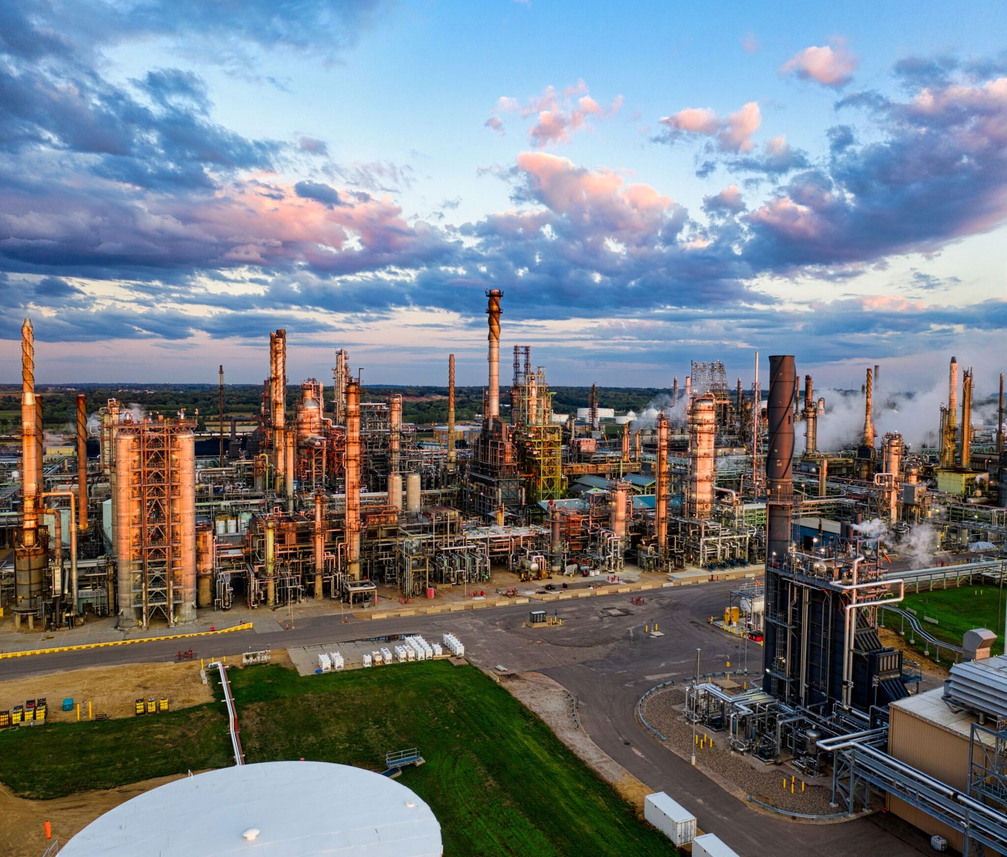
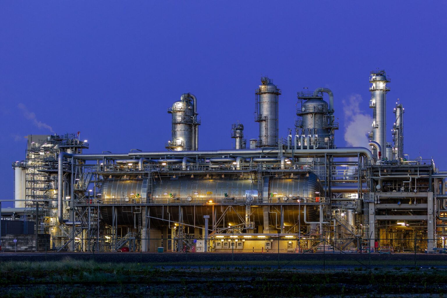
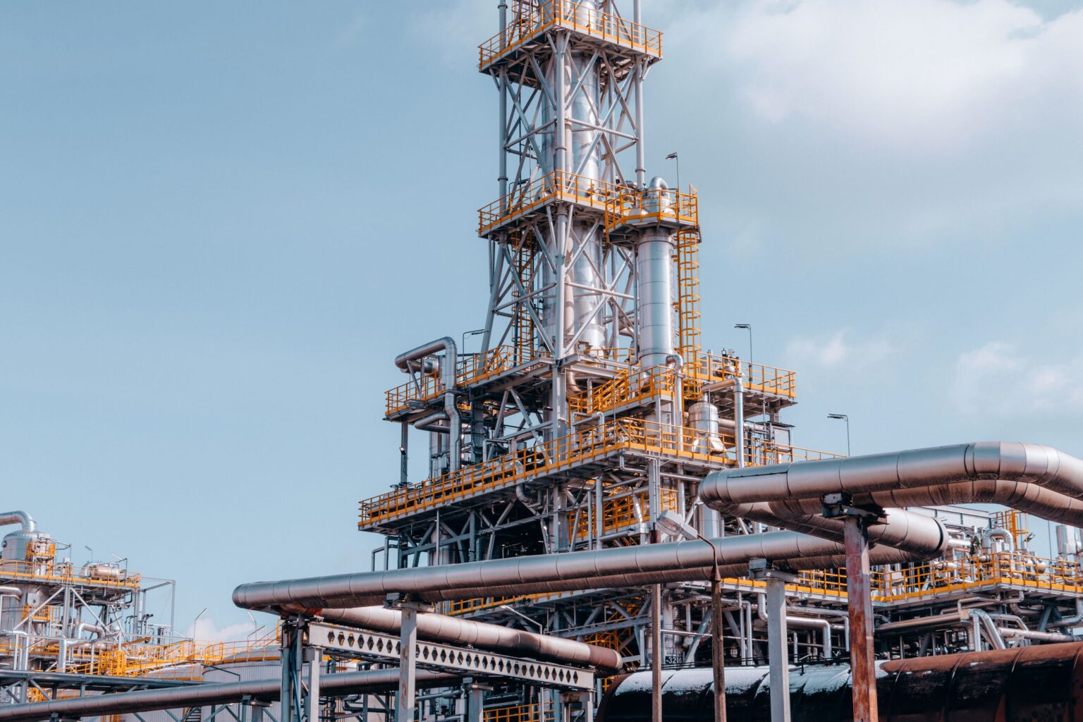
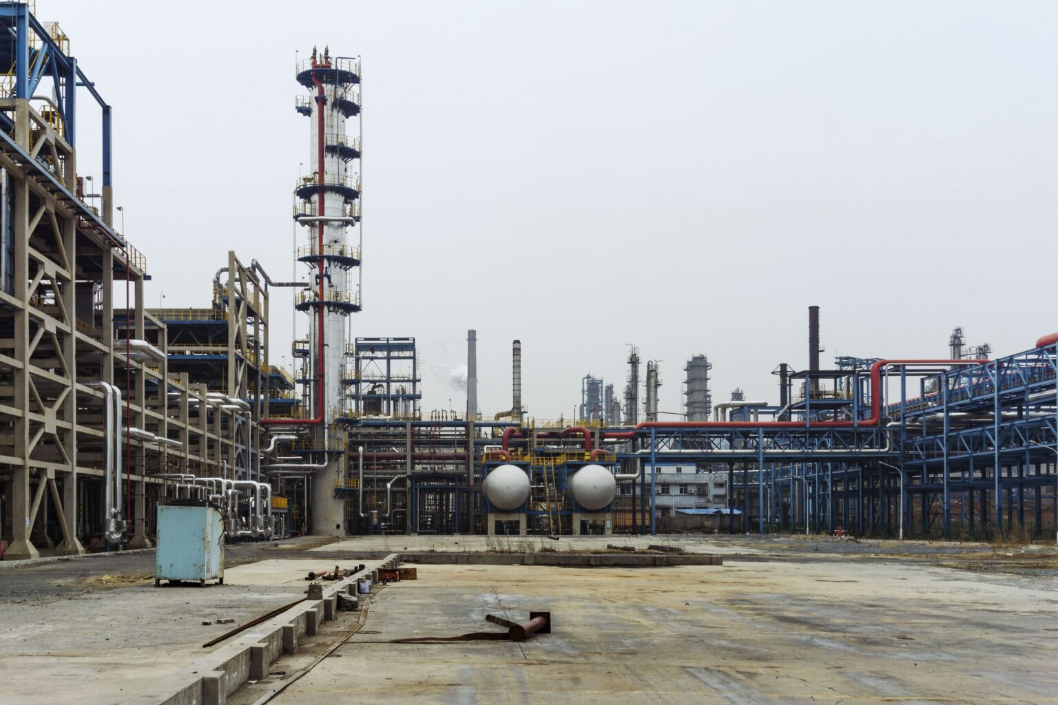
Photographs are royalty-free stock images used for illustration only. They are representative industrial views — they do not depict any licensor’s design, any client plant, or any specific reformer described in this article.
6. Steam reforming versus autothermal reforming
There are two dominant routes from a methane-rich gas to syngas at industrial scale, and the difference between them comes down to a single question: where does the heat come from?
Steam Methane Reforming (SMR)
In an SMR the heat is supplied from outside the reaction space. Desulfurised feed is mixed with steam, preheated in the convection section, and passed downward through a large number of vertical alloy tubes packed with a supported nickel catalyst. Those tubes hang inside a fired box. Burners — on the roof, on the walls, or in terraces depending on the design philosophy — heat the tube exteriors by radiation, and that heat conducts through the tube wall and drives the endothermic reaction inside.
What comes out is a hot syngas with a high hydrogen content, some carbon monoxide and carbon dioxide, unconverted methane (the methane slip), and a large excess of steam. Broadly typical outlet conditions in open literature fall in the range of roughly 800–900 °C and 15–40 bar, at steam-to-carbon ratios of about 2.5–3.5 for hydrogen and ammonia service TYPICAL RANGE.
Strengths: no oxygen plant is required, which removes a large capital item and a significant parasitic power load. The technology is extremely mature and well understood. It yields a high H2/CO ratio, which suits hydrogen and ammonia production. Heat recovery from the flue gas is well developed and the overall thermal efficiency of a well-integrated unit is high.
Limitations: the fired box is a large, expensive, metallurgically demanding structure whose cost scales awkwardly — at very large capacities you are building an enormous furnace. Heat must cross a tube wall, which caps the achievable outlet temperature and therefore the achievable methane conversion. Tube metallurgy is a lifetime-limiting item. And the flue gas leaves a dilute, atmospheric-pressure CO2 stream that is comparatively expensive to capture.
Autothermal Reforming (ATR)
In an ATR the heat is generated inside the reactor by burning part of the feed. Preheated feed and steam enter a refractory-lined vessel through a specially designed burner, together with oxygen or enriched air. A sub-stoichiometric combustion zone forms immediately below the burner, reaching very high temperatures. The hot gas then passes into a fixed bed of nickel catalyst where steam reforming and the shift reaction bring the mixture toward equilibrium.
The name says it: the reactor is thermally self-sufficient. The exothermic partial oxidation supplies the heat that the endothermic reforming consumes, with no tube wall in between. Because the heat is generated in the gas rather than conducted through metal, ATR outlet temperatures can be considerably higher than SMR — commonly quoted in the region of 950–1100 °C TYPICAL RANGE — and operating pressures can be higher too. Steam-to-carbon ratios are typically much lower than SMR.
Strengths: a compact vessel instead of a furnace, so the capital cost scales much better to very large capacity. Lower steam consumption. A syngas rich in carbon monoxide, which suits methanol and Fischer–Tropsch. And the carbon leaves in a single, concentrated, high-pressure process stream, which makes carbon capture markedly cheaper — the reason ATR features so heavily in low-carbon hydrogen schemes.
Limitations: it needs oxygen, and an air separation unit is a major capital and power item that only makes sense above a certain scale. The burner is a critical, high-duty component operating in a soot-forming regime; burner design and the avoidance of soot at low steam-to-carbon are the demanding parts of the technology. Refractory condition is a lifetime item. And the H2/CO ratio is lower, so a plant that wants pure hydrogen has more shift work to do.
| Parameter | Steam methane reforming | Autothermal reforming |
|---|---|---|
| Heat source | External firing; heat conducted through tube walls | Internal partial oxidation of part of the feed |
| Oxygen requirement | None | Oxygen or enriched air; usually an air separation unit |
| Furnace requirement | Large fired box with burners, radiant and convection sections | No fired furnace; a refractory-lined vessel with a burner |
| Reactor configuration | Many parallel alloy catalyst tubes | Single vessel: combustion zone above a fixed catalyst bed |
| Typical outlet temperature | Roughly 800–900 °C TYPICAL | Roughly 950–1100 °C TYPICAL |
| Typical steam/carbon | Higher; commonly around 2.5–3.5 TYPICAL | Substantially lower |
| Syngas H2/CO ratio | High — hydrogen-rich | Lower — carbon-monoxide-rich |
| Feed flexibility | Sensitive to heavy ends; often needs pre-reforming | Tolerant of a wider feed slate |
| CAPEX character | Furnace and tube metallurgy dominate; scales poorly to very large size | Vessel is cheap; the oxygen plant dominates; scales well |
| Efficiency character | High with good heat integration; exports significant steam | High, but oxygen production consumes power |
| Scale considerations | Well suited to small and medium capacity | Favoured at very large single-train capacity |
| CO2 implications | CO2 split between process gas and dilute flue gas — capture is harder | Nearly all carbon in one concentrated pressurised stream — capture is easier |
| Typical applications | Hydrogen plants, refinery hydrogen, ammonia front ends | Large methanol, gas-to-liquids, large-scale low-carbon hydrogen |
Neither is universally better. The honest engineering answer is that the choice is set by three things: the capacity, the required syngas composition, and whether the carbon has to be captured. A 20 000 Nm³/h refinery hydrogen unit and a world-scale gas-to-liquids front end are not solving the same problem. Combined arrangements — a fired reformer followed by an oxygen- or air-blown secondary stage — exist precisely because the two mechanisms complement each other, and classical ammonia plants have used exactly that arrangement for decades.
7. The downstream product defines the syngas
Here is the logic that beginners find counter-intuitive: the reformer is designed backwards, from the product.
| Product | What the synthesis step needs | Consequence for the reforming section |
|---|---|---|
| Hydrogen | Maximum H2; CO and CO2 are intermediates to be converted and removed; N2 is dead weight | High steam/carbon, high severity, maximum conversion, then heavy shift duty. Feed inerts are penalised hard. |
| Ammonia | H2 and N2 at close to 3:1; carbon oxides are poisons to the synthesis catalyst and must be reduced to trace levels | Nitrogen is deliberately introduced with process air in a secondary reforming stage; residual methane must be low because it is an inert in the loop. |
| Methanol | A stoichiometric number of roughly 2 — (H2−CO2)/(CO+CO2) ≈ 2.0–2.1 TYPICAL; a hydrogen-rich gas is wasteful | Lower H2/CO wanted, so CO2 import, lower S/C, or an oxygen-blown route becomes attractive. |
| Fischer–Tropsch / GTL | H2/CO close to 2 (cobalt) or lower (iron); CO2 largely unwanted | Strongly favours oxygen-blown reforming at low steam/carbon; carbon-formation control becomes the dominant design constraint. |
| Oxo / carbonylation chemistry | H2/CO near 1, or CO alone | Very low H2/CO; CO2 recycle and dedicated separation become central. |
Therefore: a reformer cannot be specified in isolation. If someone hands you a reformer duty without telling you what the plant makes, you do not yet have a design basis — you have an arithmetic exercise.
8. The first engineering decision: pressure
Now we leave chemistry and enter engineering. Ask a student what pressure a reformer should run at and the answer is usually “low, because the reaction produces more moles.” That answer is thermodynamically correct and economically wrong, and understanding why is a genuine step up in engineering maturity.
What thermodynamics says
The three reactions that matter:
Reactions (1) and (2) each convert two moles of reactant into four moles of product. By Le Chatelier’s principle, raising the total pressure pushes an equilibrium toward the side with fewer moles — here, backward, toward unreacted methane. Reaction (3) has no change in mole number and is essentially indifferent to pressure.
The consequence is unambiguous: at constant temperature and steam ratio, raising pressure increases methane slip. If equilibrium conversion were the only consideration, you would reform at the lowest pressure you could manage.
Two levers can be used to claw the conversion back. You can raise temperature, because both reforming reactions are endothermic and equilibrium therefore moves forward with temperature. Or you can raise the steam-to-carbon ratio, because steam is a reactant on the left-hand side. Both cost money, which brings us to the real question.
What economics says
A reformer does not exist in isolation. Look at where the gas came from and where it is going.
It came from a pipeline, quite possibly at a pressure well above what the reformer wants. It is going to a shift section, then to purification, then to a synthesis loop or a delivery header — and those downstream steps frequently want higher pressure than the reformer outlet. An ammonia synthesis loop, a methanol loop, a PSA-fed hydrogen header: all of them need pressure.
So if you reform at low pressure, you have to put the pressure back afterwards. And that is expensive in a particularly unpleasant way, because the syngas leaving the reformer has a very low molecular weight. Compression work per unit mass scales inversely with molecular weight, so compressing hydrogen-rich syngas is far more work than compressing the natural gas feed that produced it.
The compression asymmetry. One mole of methane produces around four moles of product gas. Compressing the feed before the reformer means compressing one mole of a relatively heavy gas. Compressing the syngas after the reformer means compressing roughly four moles of a very light gas. In almost every case it is cheaper to compress on the feed side. This single observation is why industrial reformers run at elevated pressure at all, despite the equilibrium penalty.
The compressor power relationship
For an ideal-gas polytropic compression the shaft power follows:
where Z is the compressibility factor, T1 the suction temperature, n the polytropic exponent, P2/P1 the pressure ratio, m the mass flow, M the molecular weight and eta the efficiency.
Read the assumptions before you use it. It assumes ideal-gas behaviour with a compressibility correction, a constant polytropic exponent across the stage, a single well-mixed gas composition, no phase change, no leakage and adiabatic operation. Real natural gas at high pressure deviates from all of these to some degree.
The important structural insight is in the exponent. Power does not scale with the pressure difference; it scales with the pressure ratio raised to a fractional power. Going from 10 to 20 bar and going from 20 to 40 bar both represent a ratio of 2 and cost broadly similar work per unit mass, even though the second step involves twice the pressure difference. Power also scales directly with suction temperature, which is why interstage cooling matters so much, and inversely with molecular weight, which is the syngas problem described above.
So what is the optimum?
The optimum reforming pressure is not the pressure at which conversion is highest. It is the pressure at which the sum of all the affected costs is lowest — the intersection of a rising equilibrium penalty and a falling compression penalty.
The competing effects, laid out honestly:
| Effect of raising reforming pressure | Direction | Why |
|---|---|---|
| Methane slip at fixed T and S/C | Worse | Equilibrium shifts backward with Δn = +2 |
| Required outlet temperature for a target slip | Higher | Temperature must compensate for the pressure penalty |
| Tube wall temperature and creep life | Worse | Higher process temperature and higher internal pressure act together on the same metal |
| Tube wall thickness and alloy cost | Higher | Hoop stress rises with internal pressure at temperature |
| Downstream compression duty | Lower | Less pressure to add to a light, high-volume gas |
| Equipment and piping volume downstream | Smaller | Higher density means smaller lines and vessels for the same throughput |
| Heat transfer per unit volume | Better | Higher mass velocity improves the inside film coefficient |
| Fuel consumption | Higher | Compensating with temperature or steam both cost heat |
Industrial fired reformers typically land somewhere in the range of about 15–40 bar at the outlet TYPICAL RANGE, with hydrogen plants often toward the middle and ammonia plants toward the upper end, precisely because that is where these curves cross for realistic equipment costs. It is a compromise, and it should be presented as one.
9. Joule–Thomson cooling and hydrate formation
This section exists because of a specific, common, and entirely avoidable mistake.
The mistake: “The pipeline delivers gas at high pressure and the reformer wants lower pressure, so we will simply let it down across a control valve.”
Do that without thinking and you will freeze the line.
What actually happens across the valve
Throttling a real gas is an isenthalpic process, not an isothermal one. Because real gases have non-ideal intermolecular forces, expansion at constant enthalpy changes the temperature. The Joule–Thomson coefficient describes this, and for natural gas at normal pipeline conditions it is positive — meaning the gas gets colder as it expands.
A commonly quoted rule of thumb for natural gas is a cooling of roughly 0.4–0.6 °C for every bar of pressure drop TYPICAL RANGE, varying with composition, pressure level and temperature. Drop 40 bar and you can lose 20 °C or more.
Why cold gas is a problem
Three separate things can go wrong as the gas cools, and they can happen simultaneously.
Water condenses. Cooling lowers the water dew point margin. Free liquid water appears in the line.
Hydrocarbons condense. If the gas contains C3+ material, cooling can cross the hydrocarbon dew point and drop liquid, which is bad news for absorbent beds and for any downstream compressor.
Hydrates form. This is the one that catches people out. Gas hydrates are ice-like crystalline clathrates in which water molecules cage light hydrocarbon molecules. They form at temperatures well above 0 °C when pressure is high — commonly at 15–20 °C at pipeline pressures with free water present TYPICAL RANGE. An operator who reasons “the gas is at 10 °C, water freezes at 0 °C, so we are fine” is about to plug a valve.
The variables that set the hydrate formation temperature are pressure (higher pressure means hydrates form at higher temperature), water content (no free water, no hydrate), and gas composition (heavier gases form hydrates more readily).
The engineering sequence
The essential move is the first one: heat before you throttle, not after. Heating downstream of the valve is too late — the hydrate has already formed at the point of lowest temperature, which is inside or immediately after the restriction. Preheating puts enough enthalpy into the gas that the post-throttle temperature lands safely above the hydrate curve with margin.
Where preheating is impractical, the alternatives are dehydration upstream to remove the water entirely, or injection of a thermodynamic inhibitor to depress the hydrate formation temperature. Both are legitimate; both cost more than a heater.
What a reformer engineer needs to take away: pressure let-down is a thermal operation, not just a hydraulic one. Every let-down station in a feed line needs a temperature check against the hydrate curve and both dew points, at the lowest credible ambient and the highest credible supply pressure — not at the design point. Beyond that, gas conditioning is its own discipline; know enough to ask the right question and to recognise the failure mode.
10. Compressor configuration
No mechanical design here — that is a specialist activity. What a process engineer needs is to understand how the feed conditions dictate the machine configuration.
The starting point is always the same two numbers: the suction pressure available at the battery limit, and the discharge pressure the reformer needs. Their ratio drives everything else.
| Parameter | What sets it | What it drives |
|---|---|---|
| Suction pressure | Supply contract minimum, minus let-down and pretreatment pressure drop | Machine size, volumetric flow, casing selection |
| Discharge pressure | Reformer inlet requirement plus all pressure drop through preheat and piping | Total head, number of stages |
| Pressure ratio | The two above | Single versus multistage; discharge temperature |
| Discharge temperature | Ratio, suction temperature, k value | Whether interstage cooling is mandatory |
| Suction temperature | Upstream heating and cooling | Power directly; higher T means more work |
| Gas molecular weight | Feed composition | Head per stage; centrifugal versus reciprocating choice |
| Turndown requirement | Plant operating philosophy | Recycle and anti-surge system sizing |
Single stage or multistage?
The deciding factor is usually discharge temperature. Compression is close to adiabatic, so the gas heats up as it is compressed, and beyond a certain ratio the discharge temperature exceeds what the materials, the seals or the lubricant can tolerate. Splitting the compression into stages with cooling between them keeps every stage within limits and, as a bonus, reduces the total power because each stage starts from a lower suction temperature.
Interstage cooling brings its own requirement: cooling condenses whatever the gas was carrying, so every interstage cooler needs a knockout drum behind it. Liquid entering a compressor stage is a serious mechanical event.
The other configuration items follow from operability rather than thermodynamics. A recycle line from discharge back to suction lets the machine keep running when the plant turns down. For a centrifugal machine, an anti-surge system is essential — surge is a flow reversal that occurs when the machine is asked for too much head at too little flow, and it is destructive.
The coupling that matters. The compressor cannot be specified before the reformer pressure is fixed, and the reformer pressure cannot be optimised without knowing what the compression costs. These two decisions are made together, iteratively. A junior engineer handed “size the feed compressor” should immediately ask what reforming pressure was assumed, and whether it is still open.
11. Inside the primary reformer
This is the heart of the article. A fired reformer is simultaneously a catalytic reactor, a fired heater and a high-temperature pressure vessel, and it has to succeed as all three at once.
The physical arrangement
The components, and what each one is really doing
Catalyst tubes
Vertical, typically in the region of 10–14 m long with internal diameters of roughly 100–150 mm TYPICAL RANGE, arranged in one or more rows and numbering from tens to several hundred depending on capacity. They are centrifugally cast from high-alloy nickel-chromium austenitic steels because they must simultaneously carry internal pressure, resist creep at metal temperatures that can approach 900 °C or more, and resist carburisation and oxidation.
These tubes are the most expensive consumable in the plant and their design life — commonly taken as around 100 000 hours TYPICAL — is a creep-rupture calculation. Creep damage accumulates exponentially with temperature. A sustained overtemperature of a few tens of degrees does not shorten tube life by a few percent; it can halve it. Every discussion in this article about avoiding hot bands, uneven firing and catalyst deactivation ultimately comes back to protecting these tubes.
The catalyst
Nickel on a refractory support — alumina, calcium aluminate or magnesium aluminate spinel — formulated for high crush strength and low pressure drop as well as activity. The shapes are elaborate: multi-hole cylinders, wagon wheels, ribbed and lobed geometries. That geometry is not decoration. It maximises external surface area per unit volume for heat transfer and reaction, while keeping the void fraction high so pressure drop stays manageable over a long tube.
Many designs load different catalyst types at different levels in the tube: a more robust, sometimes alkali-promoted formulation at the top where the gas is coldest, the heavy hydrocarbons are still present and carbon risk is greatest; a higher-activity formulation lower down where the duty is conversion.
Catalyst is deactivated by sulfur poisoning (partly reversible), by carbon laydown, by thermal sintering of the nickel crystallites at excessive temperature, and by physical breakage during loading or thermal cycling. Broken catalyst is particularly insidious: fines migrate, block the bed, raise pressure drop in one tube out of hundreds, and starve that tube of flow. A starved tube is a hot tube.
Burners and the radiant box
Firing arrangements differ — burners in the roof firing downward alongside the tubes, burners in the side walls in terraces, or burners at the floor firing upward. Each geometry produces a different heat flux profile along the tube, and that profile is one of the genuine differentiators between furnace designs.
The mechanism is overwhelmingly radiation. At flame and refractory temperatures, radiative heat transfer varies with the fourth power of absolute temperature and dominates convection completely. The tubes receive radiation directly from the flames and, importantly, from the hot refractory walls. This is why the box geometry, the tube spacing and the tube-to-wall distance are as much a part of the thermal design as the burner itself.
Uniformity is the objective. Tubes are in parallel, hydraulically coupled only at the inlet and outlet headers, so any tube that receives more heat or less flow than its neighbours runs hotter. A single badly adjusted burner can shorten the life of the tubes near it.
The convection section
Flue gas leaves the radiant box still extremely hot — typically in the region of 950–1050 °C TYPICAL RANGE. Letting that go up the stack would be economically indefensible, so it passes through a bank of coils that recover heat in descending order of temperature: mixed feed preheat, steam superheat, feed preheat, steam generation, combustion air preheat, and finally boiler feedwater or demineralised water heating.
The coils are arranged in that order for a reason: the highest-temperature duty gets the highest-temperature flue gas. The stack temperature is then set by an economic trade-off against the acid dew point of the flue gas — go too low and you condense acid on the cold coils.
It is worth internalising that the convection section can account for a very large share of the total heat recovered in the unit. A fired reformer that is judged only on its radiant duty is being judged on less than half the story.
Outlet system and transfer line
The tube outlets collect into headers and a transfer line carrying gas at the highest temperature anywhere in the process. These are refractory-lined with a cooled or protected metal shell, because no practical alloy will carry the pressure at that temperature unprotected. Refractory integrity in the transfer line is a critical inspection item: a hot spot on the shell means the internal lining has failed.
Pressure drop and flow distribution
Pressure drop through a 10–14 m packed bed is significant and is a real design constraint. But the reason it is monitored obsessively in operation is diagnostic rather than hydraulic. Because the tubes are in parallel, differences in pressure drop between tubes redistribute the flow. More resistance in one tube means less flow through it; less flow means less heat absorbed by reaction; less heat absorbed means a hotter tube wall; a hotter wall means faster creep and more carbon formation, which raises the resistance further.
That is a positive feedback loop, and it is the mechanism behind most reformer tube failures. A rising overall pressure drop at constant throughput is one of the earliest warnings that catalyst is breaking down or carbon is depositing.
Firing arrangements, flux profiles and catalyst
Three things decide how evenly heat arrives at the tubes and how well it is used: where the burners are, what flux profile that produces, and what the catalyst inside the tube can do with it.
12. Reforming reaction chemistry
The reactions that produce the product:
Both occur simultaneously on the same nickel catalyst inside the tube. The shift reaction is fast and stays close to equilibrium throughout, which means the CO/CO2 split at the reformer outlet is essentially set by the outlet temperature and the steam content, not by anything you do separately. Detailed shift reactor design is outside this article’s scope; what matters here is that shift is already happening inside the reformer and shapes the gas you deliver.
The behaviour follows directly from the thermodynamics. Higher temperature increases conversion because the dominant reaction is endothermic. Higher pressure decreases conversion because moles increase. Higher steam-to-carbon increases conversion because steam is a reactant, and it also suppresses carbon. Longer residence time and higher catalyst activity both bring the outlet closer to equilibrium.
The reactions that destroy the plant
Three carbon-forming reactions compete with the useful chemistry, and understanding them is the difference between operating a reformer and merely running it.
Read the temperature dependence carefully. Methane cracking is favoured at high temperature; the Boudouard and CO reduction routes are favoured at lower temperature. There is therefore no single temperature that is safe from carbon — there are different carbon mechanisms at different points along the tube. The top of the tube is exposed to the low-temperature routes and to heavy-hydrocarbon cracking; the bottom is exposed to methane cracking.
Carbon does its damage in several ways. It physically blocks catalyst pores and active sites. It builds up in the bed and raises pressure drop, triggering the maldistribution feedback loop described earlier. Filamentous carbon growing from nickel crystallites can physically fracture catalyst pellets. And because carbon-covered catalyst cannot absorb heat by reaction, the tube wall above it overheats.
The defences, in order of importance: maintain adequate steam-to-carbon ratio, because steam gasifies deposited carbon as fast as it forms; remove or pre-reform heavy hydrocarbons before the radiant tubes; keep sulfur out, since a poisoned catalyst runs hot and hot catalyst cracks methane; fire evenly, because carbon forms first wherever the flux is highest; and never let steam-to-carbon fall during a transient, which is why low-steam trips exist on essentially every reformer ever built.
Dry reforming — CH4 + CO2 <=> 2 CO + 2 H2 — also proceeds whenever CO2 is present. It is more endothermic than steam reforming, lowers the H2/CO ratio, and increases carbon-formation tendency because it adds carbon without adding hydrogen. It is exploited deliberately in some methanol and CO-rich syngas schemes, and it is the reason feed CO2 must be part of the design basis rather than an afterthought.
13. Kinetics versus equilibrium
Most textbooks teach reforming as an equilibrium problem. That is a useful first approximation and a dangerous stopping point.
Thermodynamics tells you the destination. At a given temperature, pressure and composition, equilibrium defines the best conversion that is theoretically achievable. It does not care about catalyst, tube length or flow rate. It is a boundary, not a prediction.
Kinetics tells you whether you get there. Reaction rate, catalyst activity, pore diffusion, film transfer and residence time determine how close the actual outlet gets to that boundary. In a real reformer the answer is “close, but never exactly.”
Industry expresses the gap as the approach to equilibrium: the difference between the actual outlet temperature and the temperature at which the measured outlet composition would be exactly at equilibrium. A well-performing reformer with fresh catalyst might show an approach of a few degrees to perhaps 10–15 °C TYPICAL RANGE. As catalyst ages or is poisoned, the approach widens — and tracking that widening over months is one of the most valuable diagnostics a plant has.
There is a further subtlety that pure equilibrium thinking hides completely. Inside a reformer tube, the reaction is severely limited by heat transfer and by diffusion into the catalyst pellet. The effectiveness factor — the fraction of the catalyst volume actually participating — is very low, because the reaction is fast relative to the rate at which reactant can diffuse into the pellet interior. Most of the reaction happens in a thin shell near the pellet surface.
Why this matters practically. Because only the outer shell is active, catalyst geometry matters more than catalyst mass. This is why reforming catalyst shapes are so elaborate, and why doubling the nickel content of a pellet does not double the performance of a tube. It also explains why a reformer that is running poorly rarely responds to simply pushing more heat in: the limitation is usually transfer, not intrinsic activity.
14. Why firing is required
Beginners sometimes assume the furnace is there to preheat the gas. It is not. It is there because the reaction itself consumes an enormous amount of energy, continuously, along the entire length of the tube.
The energy path is worth tracing explicitly. Burner combustion releases heat into the box. Radiation carries it to the tube outer surface. Conduction carries it through the tube wall. Convection and conduction carry it from the inner wall into the flowing gas and into the catalyst. Reaction absorbs it. Whatever the reaction does not absorb, the metal has to hold.
This is the single most important safety concept in reformer operation. The chemical reaction is the tube’s cooling system. If the reaction slows for any reason — loss of feed, loss of steam, catalyst deactivation, carbon deposition, flow maldistribution — while firing continues, the heat has nowhere to go and the tube wall temperature climbs immediately. Every reformer interlock philosophy is built around this fact.
A useful order-of-magnitude picture: of the heat released by the burners, roughly half is absorbed by the process in the radiant section, a large further fraction is recovered in the convection section, and the remainder leaves as stack loss and casing loss TYPICAL, ORDER OF MAGNITUDE. The exact split varies with design, but the message is that the radiant box alone is not where the economics are decided.
15. The heat balance is an economic story
Presented as a calculation, the heat balance is dull. Presented properly, it is the plant’s profit and loss account.
In a well-integrated hydrogen or ammonia front end, feedstock and fuel together dominate the cash cost of production — commonly quoted as the large majority of operating cost for natural-gas-based hydrogen TYPICAL. That means the heat balance is not a checking calculation performed at the end of the design. It is the design.
What the recovered heat is doing
| Recovery duty | Heat source | Economic effect |
|---|---|---|
| Mixed feed preheat | Hottest convection zone | Reduces radiant duty needed for sensible heating, so more of the radiant box does reaction work |
| Steam superheat | High-temperature convection | Raises the value of exported steam and drives steam turbines |
| Steam generation | Process gas waste heat boiler and convection coils | Displaces fired boiler duty elsewhere on the site |
| Combustion air preheat | Mid-temperature convection | Directly reduces fuel firing for the same absorbed duty — one of the highest-leverage items |
| BFW / demin water heating | Coolest convection zone | Lowers stack temperature and raises overall thermal efficiency |
The right mental model: a fired reformer is a chemical reactor bolted onto one of the largest heat-integration systems on the site. Engineers who treat it only as a reactor consistently under-perform on energy, and energy is where the money is.
What poor heat recovery actually costs
Let the heat recovery degrade — fouled convection coils, air preheater bypassed, high excess air, a leaking damper — and the consequences compound. Fuel consumption rises for the same production. Stack temperature rises, taking useful energy out of the plant. Steam generation falls, so the shortfall must be made up by a fired boiler somewhere else. Specific energy consumption per tonne of product rises. And because the CO2 emission of the plant is essentially proportional to the carbon burned, the carbon footprint rises in direct proportion — which in a carbon-priced market is now a cash cost, not a reporting line.
Illustrative only ILLUSTRATIVE — if a unit fires 100 units of fuel energy and recovers 85 of them into useful process and steam duty, then a degradation that drops recovery to 78 requires roughly 9% more fuel to hold production, with a proportional rise in CO2. The arithmetic is trivial. The point is that a few percentage points of recovery efficiency, sustained over a year on a large unit, is a very large number.
16. What the operator is actually trying to control
Everything above is design. This section is about the shift. An operator is holding several competing objectives in tension, all day, with instruments that only partially show what is happening inside the tubes.
| What is watched | Why | What it warns of |
|---|---|---|
| Reformer outlet temperature | Sets methane slip and equilibrium approach | Conversion drifting; firing imbalance |
| Tube skin temperature | Directly determines creep life | Carbon, poisoning, maldistribution, burner faults |
| Steam-to-carbon ratio | The primary defence against carbon | The most safety-critical single variable |
| Methane slip in the outlet | The performance measure | Catalyst ageing; insufficient severity |
| Bed pressure drop | Integrity of the catalyst bed | Carbon laydown, catalyst breakage, fouling |
| Furnace draft | Combustion stability and containment | Positive pressure in the box; air in-leakage |
| Excess oxygen in flue gas | Combustion efficiency | Too low means incomplete combustion; too high wastes fuel |
| Flue gas / stack temperature | Heat recovery health | Fouled or bypassed convection coils |
| Flame pattern and burner condition | Uniformity of heat flux | Flame impingement on tubes — a rapid killer |
The six trade-offs, and what happens when you get them wrong
Steam-to-carbon ratio too LOW
Carbon formation begins on the catalyst. Deposits block active sites, so the reaction slows locally. Because the reaction is the tube’s cooling mechanism, the wall above the deposit overheats and hot bands appear. Carbon builds, pressure drop rises in the affected tubes, flow diverts to easier tubes, and the affected tubes get hotter still. Left alone this ends in tube rupture. This is why low steam-to-carbon is an automatic trip and not merely an alarm.
Steam-to-carbon ratio too HIGH
Nothing breaks — it just costs money continuously. Excess steam must be raised, superheated, pushed through the tubes, heated to reaction temperature, and then condensed and separated downstream. It raises the reformer heat duty, increases pressure drop, and consumes boiler feedwater and its treatment. It also dilutes the gas, which increases the volumetric load on every downstream item. Running a permanently high steam ratio is the most common way to hide an underlying problem while paying for it every hour.
Outlet temperature too LOW
Equilibrium conversion falls and methane slip rises. Unconverted methane is wasted feedstock, and it becomes an inert in a synthesis loop that then has to be purged — so the loss is amplified downstream. In a hydrogen plant it ends up in the PSA tail gas, where it has fuel value but not product value.
Outlet temperature too HIGH
Conversion improves, but tube metal temperature rises and creep damage accumulates exponentially. Catalyst sinters and loses surface area permanently. Methane cracking becomes thermodynamically more favourable. The gain in conversion is real and immediate; the cost is deferred, invisible and irreversible — which is exactly why it is a tempting mistake.
Pressure too HIGH
Equilibrium moves backward and methane slip rises. To compensate you must raise temperature or steam ratio, both of which cost heat, and the higher pressure simultaneously increases hoop stress on tubes that are already at their thermal limit.
Pressure too LOW
Conversion improves, but every downstream compressor has to make up the difference on a low-molecular-weight gas, at high volumetric flow, in a machine that was sized for a design case. Equipment volumes upstream of that compression are also larger for the same throughput.
The unifying insight: almost every reformer upset shows up first as a thermal symptom, because the reaction is the cooling system. Learn to read tube skin temperature and pressure drop trends together and you can usually diagnose a reformer before the composition analysers notice anything at all.
17. How configuration changes with the application
| Design feature | Hydrogen plant | Ammonia front end | Methanol plant | FT / GTL syngas |
|---|---|---|---|---|
| Target H2/CO | As high as possible | H2 maximised; carbon oxides removed entirely | Stoichiometric number near 2 | Near 2, CO-rich |
| Nitrogen | Undesirable inert | Required reactant, added deliberately | Undesirable inert | Undesirable inert |
| Typical technology | Fired reformer, often with pre-reforming | Fired primary plus air-blown secondary | Fired reformer, combined, or oxygen-blown by scale | Oxygen-blown reforming |
| Steam/carbon character | High | High | Moderate | Low — carbon control is the constraint |
| Reforming severity | High — minimise slip | Very high — methane is a loop inert | Moderate | Very high |
| CO2 handling | Shifted and removed or captured | Removed completely before synthesis | Often retained or imported to correct the ratio | Generally minimised |
| Downstream pressure driver | Delivery header or PSA | High-pressure synthesis loop | Synthesis loop | Synthesis reactor |
| Syngas conditioning | Full shift plus purification | Full shift, CO2 removal, methanation | Ratio adjustment, partial shift | Partial shift or none; CO2 removal |
Reading across a row is the exercise. The same unit operation is being tuned toward four different targets, and the design decisions that look arbitrary in isolation are entirely determined once you know which column you are in.
18. Worked numerical examples
Every example below is ILLUSTRATIVE. The assumptions are stated so you can follow the method; the numbers are teaching numbers, not design numbers, and they do not represent any operating plant.
Example 1 — Steam-to-carbon ratio for a feed containing heavy ends
Assumptions: feed of 100 kmol/h containing 90% CH4, 5% C2H6, 2% C3H8, 2% CO2, 1% N2. Target S/C = 3.0 on total hydrocarbon carbon.
Lesson: 7 mol% of C2/C3 raised the steam demand by 6% at identical molar feed. Put the other way round: if the steam flow controller is holding the pure-methane setpoint and the feed turns rich, the actual S/C has silently fallen to about 2.83 — and the operator sees nothing on the panel unless the ratio is computed from a live analysis.
Note also the CO2. Whether feed CO2 is counted in the S/C denominator is a convention that differs between organisations. If it were counted here, the carbon becomes 108 kmol/h and the steam requirement 324 kmol/h. Always establish which convention a number was quoted on before comparing two plants.
Example 2 — Joule–Thomson temperature drop and hydrate margin
Assumptions: supply at 55 barg and 25 °C, let down to 30 barg. J-T coefficient taken as 0.5 °C/bar. Hydrate formation temperature at 30 barg with free water present assumed to be 15 °C.
Now add preheat upstream of the valve to 45 °C:
Lesson: the fix is upstream heating, and the required preheat comes straight out of the arithmetic. Check it at the lowest credible supply temperature and the highest credible pressure drop, not at the design point — that is where the margin disappears.
Example 3 — Multistage compression and the pressure-ratio rule
Assumptions: ideal gas, k = 1.31, suction 5 bara at 40 °C, discharge 40 bara.
Lesson: splitting the ratio and cooling between stages dropped the discharge temperature from 219 °C to 122 °C, bringing it inside normal material and seal limits — and it reduces total power as well, because the second stage starts cold. Equal ratio per stage is the classic first estimate for minimum total work.
Example 4 — Reformer heat duty, first-pass estimate
Assumptions: 100 kmol/h methane fed, 92% conversion, heat of reaction for CH4 + H2O → CO + 3H2 taken as 206 kJ/mol at 298 K. Sensible heating of feed and steam from 500 to 850 °C estimated at 35% of the reaction duty for this illustration.
Lesson: the reaction is only part of the duty, and roughly half of what you fire never reaches the process in the radiant box. Whether that half is recovered or thrown away is the difference between an efficient plant and an expensive one.
Example 5 — The economic cost of one degree of efficiency
Assumptions: a unit firing 50 MW of fuel, 8000 operating hours per year, fuel valued at USD 8 per GJ, natural gas emission factor 56 kg CO2 per GJ.
Lesson: one percentage point. That is the value of keeping the convection coils clean, the excess oxygen trimmed and the air preheater in service. Multiply by the number of percentage points a neglected unit typically loses and the case for condition monitoring writes itself.
Try it yourself — steam-to-carbon calculator
Enter a feed composition in mol% and a target S/C ratio. The tool computes hydrocarbon carbon and the steam requirement, and shows what happens if the steam rate is left at the pure-methane setpoint.
19. Oversimplifications to avoid
A short list of statements that sound reasonable, appear in introductory material, and will mislead you.
| The oversimplification | Why it is wrong |
|---|---|
| “The reformer reaches equilibrium.” | It approaches equilibrium. The size of the approach, and how it changes over time, is the primary diagnostic of catalyst health. |
| “More steam is always safer.” | More steam is safer against carbon and expensive against everything else. Permanently high steam usually means an unaddressed problem. |
| “Lower pressure is better because more moles are formed.” | True thermodynamically, frequently false economically, because the pressure has to be put back into a very light gas downstream. |
| “Sulfur just reduces catalyst activity.” | Sulfur causes a thermal failure mode. Lost activity means lost heat absorption means overheated tubes. |
| “CO2 is an impurity.” | CO2 is a reactant that changes the product ratio, the duty and the carbon margin. |
| “Nitrogen is inert so it does not matter.” | It is dead load for a hydrogen plant and a raw material for an ammonia plant. It always matters, just with opposite sign. |
| “Higher temperature always improves the reformer.” | It improves conversion today and consumes creep life permanently. Creep damage is exponential in temperature. |
| “Just let the pressure down with a valve.” | Throttling is isenthalpic, the gas cools, and hydrates form well above 0 °C at pressure. |
| “Carbon forms only at high temperature.” | Methane cracking is favoured hot; Boudouard and CO reduction are favoured cold. Different mechanisms, different parts of the tube. |
| “The catalyst does the work, so more catalyst mass is better.” | The effectiveness factor is very low. Only a thin outer shell reacts, so geometry beats mass. |
| “SMR and ATR are competing technologies, one of which wins.” | They solve different problems at different scales with different carbon-capture economics, and are frequently combined. |
| “The heat balance is a checking calculation.” | Fuel and feedstock dominate operating cost. The heat balance is the design. |
20. Self-check
Q1. A reformer’s tube skin temperatures are rising steadily at constant firing rate, constant feed rate and constant outlet temperature setpoint. Composition analysers show a slow rise in methane slip. What is the most likely underlying cause?
Q2. Pipeline gas at 60 barg and 20 °C is throttled to 25 barg. Water is present. What must be checked first?
Q3. A plant switches from a lean pipeline gas to a richer gas with more ethane and propane, holding the steam flow controller at its previous setpoint. What happens?
Q4. Why is it usually cheaper to compress on the feed side of a reformer than on the syngas side?
Where to read further
This article deliberately cites categories of source rather than proprietary documentation. For deeper study, the most reliable open material is found in: standard chemical engineering texts on hydrogen and synthesis gas manufacture; peer-reviewed literature on nickel reforming catalysts, carbon formation mechanisms and reforming kinetics; published technical papers from ammonia, methanol and hydrogen safety and technical symposia; catalyst manufacturers’ publicly issued technical bulletins; national laboratory and government technical reports on hydrogen production pathways and life-cycle emissions; and international standards covering fired heater design, gas dehydration and hydrate prevention.
A closing note on scope. Everything here is generic, publicly documented engineering. Specific reformer geometries, burner arrangements, catalyst formulations, heat-flux profiles and integration schemes are proprietary to the organisations that developed them, and any real project should be executed with the licensor’s own documentation and a competent design contractor. The purpose of this article is to make you a better-informed engineer in that conversation — not to substitute for it.
The one-paragraph summary
A reformer converts a methane-rich gas into a synthesis gas of specified composition. What enters it determines how it must be pretreated. What the plant ultimately makes determines the composition it must produce, and therefore the technology, the severity and the steam ratio. Pressure is an economic compromise between equilibrium and compression, not a thermodynamic optimum. Getting the gas from the pipeline to the tubes involves real thermal hazards that have nothing to do with chemistry. And inside the tubes, the endothermic reaction is the only thing keeping the metal alive — which is why every operating decision eventually comes back to heat.
Have a reforming question of your own?
A feed analysis you are not comfortable with, a steam-to-carbon argument that needs settling, a tube-skin trend that is drifting, or a hydrogen, ammonia or methanol project still at the concept stage — send the question across and it will be read and answered personally.