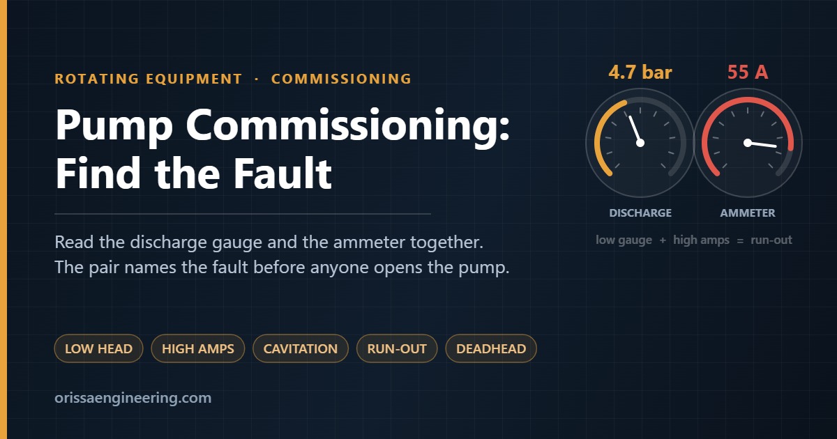
Dark technical card reading Pump Commissioning: Find the Fault, with a discharge pressure gauge at 4.7 bar and an ammeter at 55 A

Pump Commissioning: Find the Fault

Four months on the plinth. Alignment signed off. Motor solo run clean. Suction flushed, temporary strainer in, discharge valve cracked two turns. The operator presses start. The motor pulls, settles — and stops matching the datasheet. The discharge gauge climbs to 4.7 bar and parks there; it should be near 6.5. The ammeter drifts past 55 A and keeps climbing. And the sentence gets said, the way it gets said at every commissioning: the pump is faulty, the engineering is wrong, we can’t take it into production.

It almost never is. What is actually happening is that the plant is telling you, for the first time and very loudly, what its real hydraulics look like — as against the ones calculated in an office before the plant existed. A first run is not a verification step; it is a measurement, and it is the cheapest moment the plant will ever offer to find and fix whatever is wrong. By the end of this page you should be able to walk up to a pump on its first run, read the gauges and the ammeter together, name one specific fault, prove it with a single test, and know which fix applies.

Scope. This page is about running the pump — the hydraulic and mechanical behaviour of a centrifugal pump on its first run during pre-commissioning. It deliberately says nothing about safety. Permits and isolation, electrical protection, relief and venting, hot, toxic or flammable service, guarding: the commissioning team must assess and manage all of that on its own, under the site’s own procedures, before and during any run described here.
Discharge nozzle Volute casing Impeller Wear ring Impeller eye — lowest pressure in the machine Suction nozzle Mechanical seal Shaft Bearings — radial + thrust Coupling velocity becomes pressure here cavitation (A5) and air locks (A1) are born here ruined in minutes if run dry — A1 / B3 verify rotation uncoupled — C1 the clearance C5 wears open baseplate
The machine in section. Liquid enters the eye, the impeller throws it outward, the volute turns velocity into pressure, and the shaft carries the story out to the seal, bearings and coupling. Every fault on this page lives at one of these parts: gas collects in the eye (Root A), the wear-ring clearance leaks (C5), the seal dies against a closed valve (B3), and the coupling is where rotation is proved (C1).

Three instruments, one equation

Everything below comes out of one statement: Pshaft = ρ·g·Q·H / η. The pump makes metres of whatever fluid is inside the impeller; the gauge reads bar; density is the bridge between them. That also makes the ammeter a density meter and a flowmeter at the same time — which is why the first rule of first runs is: read the discharge gauge and the ammeter together, never separately. A low gauge with low current means the pump is not moving liquid. A low gauge with high current means it is moving far too much. Those are opposite problems, and the bench below is built around telling them apart.

AMMETER LOW / NORMAL AMMETER HIGH GAUGE LOW GAUGE ON THE CURVE A · C Not moving liquid Gas where liquid should be, or not the curve you think: air lock, reverse rotation, wrong impeller, wrong speed. The motor idles near no-load. Test: vent + restart · tachometer · shut-off check B Moving far too much The system was easier than calculated — flow ran away right of BEP. Head fell, current climbed: the pump is working harder, not weaker. Test: throttle back — both readings recover E Hydraulically healthy Point sits on the curve at a workable flow. If it still shakes, roars or runs hot, the curve is innocent — the problem is mechanical. Test: vibration analyser — 1×, 2×, vane-pass D Right machine, wrong fluid Head and flow on the curve, current high by a clean ratio — density above design. Viscosity drags head down and power up at the same time. Test: expected current × (actual SG ÷ design SG)
The first look, before any theory. Read the discharge gauge and the ammeter together — the pair names the root family. Either instrument alone lies: a low gauge is two opposite faults until the ammeter breaks the tie.

The commissioning bench

Enter the pump you are standing in front of. The bench draws the expected curve, places your gauge and ammeter readings on it, and then walks you from the deviation you can see to the one fault that explains it — and its fix.

Step 1 — The pump you are standing at

Nameplate data is enough. The bench generates an indicative expected curve from it — confirm against the vendor’s tested curve before any final decision.

Step 2 — What the instruments say (optional, but this is where the bench earns its keep)

Type what you actually read on the running pump. The bench places the point on the curve and reads the gauge and ammeter together for you.

Expected curve Indicative fault pattern Your reading Motor rating
Reference numbers — the step table

Record exactly this triplet — suction pressure, discharge pressure, current — at each valve step on the real run. Three filled rows are usually enough to name the fault.

Step 3 — Pick the deviation you can see

Each card lists what that deviation can mean; the questions then separate the candidates one test at a time.

Reference model: shut-off head ≈ 0.57·u²/g, shut-off ≈ 1.2 × BEP head, pump η ≈ 75% at BEP, motor η ≈ 93%. Fault patterns are indicative shapes for recognition, not predictions. Always confirm against the manufacturer’s tested curve.

What the faults look like inside the machine

The bench names a fault code; these are the six mechanisms behind most first-run arguments, drawn at the part of the machine where they actually happen. Pick a deviation card in Step 3 and the matching sketch also appears beside the verdict.

P dips below vapour pressure — bubbles grow… …and collapse: pitting starts vane, seen along the shaft
A5 — Cavitation. Bubbles form where pressure dips under vapour pressure at the vane inlet and implode a few centimetres in: gravel noise now, pitted vanes at the overhaul. Throttling back calms it — that is the field test.
submergence air core reaches the offtake air to the pump runs clean when full — fails at the same drawdown
A2 — Vortexing. Below critical submergence the surface dimple grows a rope of air straight into the offtake. It tracks tank level exactly — and the proof is a look into the tank.
correct reversed still pumps — quietly wrong full head ≈ half
C1 — Reverse rotation. Backwards, a centrifugal pump still pumps — near half head at lower power, steady from the first second. Prove rotation with the coupling removed, never on word alone.
discharge side — high P eye — low P leak-back clearance worn open impeller shroud casing
C5 — Worn wear rings. Discharge-pressure liquid short-circuits through the opened clearance back to the eye: full work, less delivered flow — and shut-off head barely changes, which is what separates it from viscosity.
design duty design system real system — flatter flow ran away head ↓ · amps ↑ Q H
B1 — Run-out. The real system was easier than the calculation: the duty slid right of BEP, head fell and current climbed past FLA. Throttle back and both instruments recover — that is the test.
parked at shut-off closed no flow all shaft power → heat in a trapped slug
B3 — Deadhead. Against a closed path, every kilowatt becomes heat in the same slug of liquid; left running it flashes inside the casing and takes the seal with it. Find which of the four blockers it is before opening anything.

Before you name a culprit

Whatever the bench suggests, prove it with its discriminating test before acting — vent and restart, raise the level, put a tachometer on the shaft, dead-head for a minute and read the gauge. And record the run: suction pressure, discharge pressure and current at each valve step. That one sheet turns a rough first morning into an engineering document — the plant’s real curve, measured while the correction is still cheap — and it is the difference between fixing a pump and arguing about one.

Tell me about your pump

If a pump on your plant is not doing what the datasheet says — low head, high current, cavitation, a first run that will not hold flow — describe it below. The message goes straight to my inbox at saswatsatpathy080390@gmail.com. Give me the duty, what the discharge gauge and the ammeter read, and what changed. That pair of readings is usually enough to name the fault family before anyone opens the pump.

    No obligation, and no mailing list. Your details are used only to answer your question.