When the Plant Says “Bad Design” — and the Physics Says Otherwise
How systematic process engineering rescued a ₹6 Crore acetic acid recovery system in 8 hours, after a week of standstill.
There is a particular kind of silence on a plant floor when an expensive new unit refuses to run. Operators stand around a DCS screen full of red alarms. Managers ask the same question every morning. And somewhere in the background, a corporate clock is ticking.
Walking Into the Fire
I walked into exactly that scene at an agrochemical manufacturing site, midway through the commissioning of a newly installed three-stage acetic acid recovery system. The lead process engineer had left abruptly, leaving behind unverified control loops and incomplete handover notes. The system — a ₹6 Crore capital investment built to recover 1,100 kg per day of glacial acetic acid from process effluent — had been stalled for seven days since water trials ended. Chemical commissioning would not stabilize, production pressure was mounting, and the consensus on the floor had hardened into a verdict:

This article is the story of why that verdict was wrong, how fifteen minutes of controlled physics changed an entire team’s mind, and why disciplined process engineering — not intuition, not blame — is what converts a struggling capital asset into a profitable one.
The System: Turning 50 wt% Waste Acid Into Glacial Product
The feed to this plant was an aqueous stream containing roughly 50 wt% acetic acid and 50 wt% water. Anyone who has studied the acetic acid–water system knows the problem: the relative volatility between the two is so unfavourable near high acid concentrations that direct distillation to glacial grade is brutally energy-intensive. The economic answer is a combined liquid–liquid extraction and heterogeneous azeotropic distillation scheme, using ethyl acetate (EtAc) as both extraction solvent and entrainer. The entire complex was fabricated in SS304 and operated at essentially atmospheric pressure (1 atm).
Liquid–Liquid Extraction
The acidic feedwater is washed with ethyl acetate (EtAc). The acetic acid prefers to dissolve into the EtAc, so it moves into the organic layer. The leftover water (the “raffinate”), still carrying a little dissolved solvent, is sent to Stage 3 to recover that solvent.
Azeotropic Distillation Column
EtAc and water form a low-boiling pair (an azeotrope) that boils at just 70.4 °C. This vapour carries every trace of water out of the top of the column. The overhead vapour is condensed into a decanter, where it naturally splits into two layers: the EtAc-rich layer flows back into the column (reflux), and the water layer goes to Stage 3.
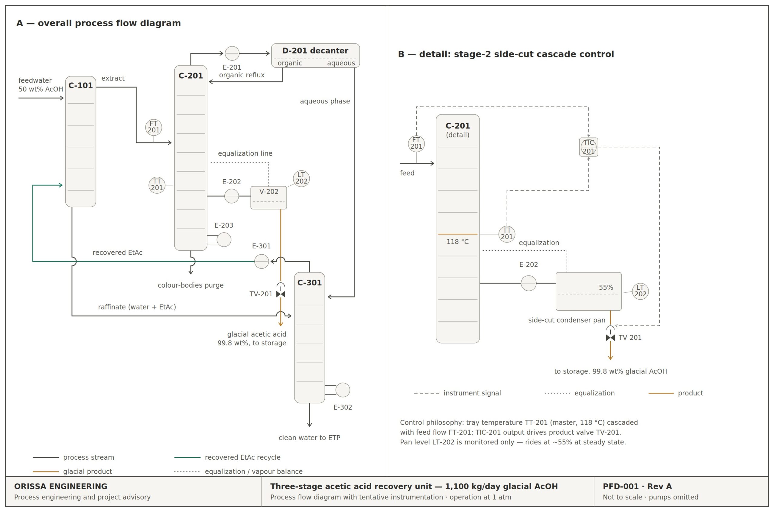
Purified acetic acid vapour is drawn from near the bottom of the column at its boiling point of about 118 °C, condensed in a dedicated side-cut condenser pan, and sent to storage at 99.8 wt% purity. This single stream is the commercial product. (The column bottoms hold dark, high-boiling colour bodies and are not recyclable.) If the side-cut fails, the plant makes nothing of value.
Solvent Stripper
The wet streams from Stage 1 and the Stage 2 decanter are boiled to recover the leftover EtAc, which goes back into the solvent loop. Clean water leaves the bottom.
Stage 1 — Extraction. The acidic feedwater is contacted with EtAc. Acetic acid partitions into the organic phase; the water-rich raffinate, carrying dissolved solvent, routes directly to Stage 3 for solvent recovery.
Stage 2 — Azeotropic distillation. The organic extract enters the main column. EtAc forms a minimum-boiling heterogeneous azeotrope with water — boiling at 70.4 °C at 1 atm, with a vapour composition of approximately 91.9 wt% EtAc and 8.1 wt% water. This azeotrope sweeps every trace of moisture out of the top of the column. The overhead vapour condenses into a continuous decanter, where it splits into two liquid phases: the organic (EtAc-rich) layer refluxes back to the column, while the aqueous layer is pumped to Stage 3.
The side-cut — the heart of the plant. Purified acetic acid vapour is drawn from near the bottom of the column at its atmospheric boiling point of about 118 °C, condensed in a dedicated side-cut condenser pan, and routed to product storage at 99.8 wt% purity. This stream is the entire commercial point of the plant — because the column bottoms carried high-boiling colour bodies and were not usable or recyclable to the process. If the side-cut failed, the plant produced nothing of value.
Stage 3 — Solvent stripping. The wet streams from Stage 1 and the Stage 2 decanter are stripped of residual EtAc, which returns to the solvent loop, while clean water leaves the bottom.
The Crisis: A Control Valve That Refused to Obey Its Own Logic
Every attempt to initiate the acetic acid side draw triggered the same cascading failure. The column temperature profile plummeted. The level transmitter (LT) on the side-cut condenser pan slammed to its upper limit. And then came the paradox that convinced everyone the instrumentation was junk: the product control valve was interlocked to open on high level — yet with the LT pegged at maximum, the valve sat stubbornly shut.
Convinced the transmitter was faulty, operations bypassed the automation and ran the loop in manual. It was unmanageable. The condenser pan cycled violently between flooding and running dry. Increasing feed flow to recover column temperature only surged the collection rate, demanding endless manual corrections. After a week of this, the plant floor had reached its verdict: a ₹6 Crore design failure, with faulty instruments thrown in for good measure.
The Investigation: Proving the Physics Before Touching the Logic
I knew that before I could fix the automation, I had to fix something harder — the mindset. The team had to see, with their own eyes, that the hardware was sound and that we were fighting mass and energy balance laws, not a broken instrument.
First, the simple check. I completely emptied the side-cut condenser pan. The LT dropped cleanly to 0% — responsive. I cracked open the manual run-off valve; as liquid refilled the pan, the LT tracked the level perfectly. And, true to form, the column temperature crashed again. The transmitter was telling the truth. Nobody was listening to what it said.
Then came the demonstration that broke the cognitive bias. I isolated the cooling water to the side-cut condenser while maintaining a slow, controlled vapour transfer. Deprived of cooling, condensation stopped — and on the live trend, the pan level began to fall in real time as vapour simply passed through uncondensed.
Watching the level respond perfectly to deliberate physical changes, the Operations Manager said what needed to be said: the LT is fine — the control philosophy is wrong.
The Engineering Solution: Let the Column’s Thermodynamics Drive the Valve
The fundamental flaw was now obvious. The side-cut valve was watching the wrong variable. Drawing product purely on condenser pan level pulled thermal energy out of the column bottom faster than the reboiler section could replace it, collapsing the temperature profile that keeps water from slipping down into the glacial acid zone at 118 °C. The “phantom” interlock paradox was just the control system faithfully executing a philosophy that contradicted the column’s own energy balance.
The reworked strategy had two elements. The product draw valve was re-mapped to the column tray temperature profile, so the draw rate became a direct function of the thermodynamic state of the separation rather than the inventory in a downstream pan. That temperature loop was then cascaded with the primary feed flow rate, so any upstream change in mass input automatically scaled the side-cut draw without thermal shock. We calculated the valve trim required for design conditions, procured and installed the correctly sized valve, and initiated a restart.
The Result: 8 Hours to Steady State

Within eight hours of restart, the column reached the steady state that had eluded the team for over a week. The side-cut temperature locked at 118 °C. Product purity held at 99.8 wt% glacial acetic acid — clear, colour-free, on specification. The condenser pan level settled at a calm 55%, riding smoothly on cascade control with no operator intervention.
The talk of “faulty column design” and “instrument errors” simply evaporated. The operators returned to their routines, and a major capital asset began doing what it was built to do: paying for itself, 1,100 kg of recovered product at a time.
What This Means for Every Chemical Manufacturer
Strip away the chemistry, and this story carries three lessons that apply to any plant — fluorochemicals, nitric acid, chlor-alkali, agrochemicals, or specialty chemicals.
Manufacturing cannot survive on intuition or guesswork. It survives on engineering.— The lesson of the eight-hour restart
Facing a Commissioning Crisis of Your Own?
This is precisely the kind of problem Orissa Engineering exists to solve. Our practice brings senior, hands-on process engineering experience across specialty chemicals, fluorochemicals, agrochemicals, nitric acid, and caustic-chlorine operations directly to your plant floor and your project team.
If a unit in your plant won’t stabilize, a commissioning is stalled, or a “design failure” verdict is hanging over a capital investment, you can post your engineering query through our consultation page — the initial submission and expert review cost nothing, and detailed work is scoped and charged only when you agree to proceed. For teams who want to build their own analytical muscle, our library of engineering calculation workbooks covers column design, heat exchanger sizing, mass and energy balances, and more — the same systematic tools used in this case study. And through our Technology Exchange, proven process packages and operating know-how can be bought or sold with complete confidentiality.
Method & Caveats
- All process figures — 50 wt% feed, the 70.4 °C EtAc–water azeotrope (~91.9 wt% EtAc / 8.1 wt% water), the ~118 °C side-cut, 99.8 wt% product purity, 1,100 kg/day capacity and SS304 construction at 1 atm — describe a real commissioning case and are representative engineering values, not licensor-guaranteed data.
- The control re-design (side-cut valve mapped to tray temperature, cascaded with feed flow) and valve-trim sizing were executed against the as-built column; equivalent loops on another column should be re-verified against its own heat-and-mass balance.
- The 15-minute cooling-water isolation test was bounded deliberately to avoid migrating un-condensed acid vapour into the vent and Stage 3 loops. Such tests should only be run with operations supervision and a clear hazard review.
Facing a commissioning crisis of your own?
Orissa Engineering provides commissioning rescue, process troubleshooting, lender’s technical advisory, and owner’s engineer services. The initial review costs nothing.
Discuss a Project
Message sent successfully
Thank you for reaching out. We will review your project details and get back to you within 1 business day.