Vacuum Steam: Latent-Heat Heating Below 30 °C
A direct-fluorination process that yielded 95% in the lab and 10% in the plant — and how a senior’s idea, steam that condenses below 30 °C, engineered into a working system, turned a batch that was losing $16,000 back into one that earns it.
In the laboratory the chemistry was sound and, on paper, profitable. In the plant, the very same recipe burned money. The gap between those two facts is a story about heat transfer — and about an idea that sounds like a contradiction: heat a batch with steam, but steam that condenses below 30 °C.
1. The Problem: A Process That Made Money in the Lab and Lost It in the Plant
The product — made by direct fluorination at −75 °C — came off the lab route at 95% yield with a projected batch cycle time of 16 hours. At about $20,000 of operating cost against $36,000 of revenue, that is roughly $16,000 of margin every time the reactor turns over. A good process to scale.
The plant told a different story. The first three batches came out at 10% yield and ran 36 hours each. Same chemistry, same recipe — but a batch that earned $16,000 in a flask was now burning about $20,000 to make roughly $3,800 of product. Scale-up had turned a money-maker into a loss of about $16,000 per batch, and tied the reactor up for more than twice as long to do it.
| Lab (proven) | Plant — first 3 batches | |
|---|---|---|
| Yield | 95% | 10% |
| Batch cycle time | 16 h (projected) | 36 h |
| Revenue per batch | $36,000 | ≈ $3,800 |
| Operating cost per batch | ≈ $20,000 | ≈ $20,000 |
| Margin per batch | + $16,000 | ≈ − $16,000 |
The cause sat in a single step, and it is a classic scale-up trap. The campaign runs a fixed sequence, each step with a hard limit:
| Step | Requirement |
|---|---|
| Reaction | −75 °C |
| Filtration of the reaction mass | −25 °C |
| Solvent recovery | distil off 60% of the charge to drive the batch to supersaturation and crystallise the product |
| Final isolation | filter the crystallised product |
| Temperature ceiling (anywhere, any time, until product is isolated) | 35 °C |
| Solvent recovery + isolation window | < 4 hours |
Two of those are degradation limits: the mass — or any wall it touches — must never exceed 35 °C, and the recovery-and-isolation window must stay under 4 hours, which sits inside the ~16-hour overall cycle. Cross either and the molecule comes apart. There is no partial credit.

In a flask none of this is hard: a small charge sees a large heated surface relative to its volume, so even a gentle medium recovers solvent fast and cool. Scale up and that advantage collapses — jacket area grows with the square of size while volume grows with the cube, so the heat-transfer area per unit charge falls away. The step that broke the campaign was the solvent recovery — boil off 60% of the charge, below 35 °C, inside the window — and at plant scale the obvious media could not do it:
Hot water, or a warm tempered loop. To move the duty through a now-modest jacket area in time, you raise the supply temperature — and the wall runs hot, and the product film against it degrades. Run it cool enough to be safe and the recovery overran the four-hour window. Either way the product was lost; in practice about 90% of it.
Low-pressure steam at or near atmospheric. Saturated steam at 1 atm sits at 100 °C — nowhere near a temperature you bring to this batch. Wholesale degradation.
(The filtration steps were handled separately, with a jacketed agitated Nutsche filter sized for the duty that held filtration to about an hour — its own piece of engineering, for another article.)
2. The Theory — The Idea a Senior Handed Us
Then a senior engineer on the team suggested something that, at first, sounded like a contradiction: heat the batch with steam — but steam that condenses below 30 °C. Vacuum steam.
The reason it works sits in the steam tables. Steam’s saturation temperature falls with its pressure; pull the pressure down far enough and you get saturated steam — still carrying its full latent heat — at a temperature you choose.
| Jacket pressure (absolute) | Steam saturation temperature |
|---|---|
| 300 mmWC (≈ 2.94 kPa) | ≈ 24 °C |
| 400 mmWC (≈ 3.92 kPa) | ≈ 29 °C |
| for reference: 10,330 mmWC / 760 mmHg / 1 atm | 100 °C |
A word on units, because this is exactly where the suggestion can be misread. The 300–400 mmWC here is absolute pressure, i.e. a deep vacuum, not a gauge reading; in gauge terms it is roughly a 730–740 mmHg vacuum. Hold the jacket in that band and the steam condenses at about 24–29 °C — comfortably under the 35 °C ceiling, with five to ten degrees of margin built in.
Once we understood what he was pointing at, the appeal was clear. Condensing steam at that temperature buys three things at once:
Latent heat at constant temperature. Steam at ~30 °C carries on the order of 2,430 kJ/kg of latent heat and releases it isothermally. A small mass flow therefore moves a large duty, and — crucially — the whole wetted surface sits at one temperature, the saturation temperature. There is no temperature glide along the jacket the way there is with water.
A very high condensing film coefficient. Condensing vapour transfers heat far better than a single-phase liquid scraping along a jacket wall, so the jacket-side resistance that dominates with hot water all but disappears. Under clean, lightly loaded conditions you can even get dropwise condensation, where the surface isn’t blanketed by a liquid film and coefficients climb higher still. That high coefficient is what claws back the heat-transfer capability scale-up took away — it lets you move the duty across a small temperature difference, the only kind a heat-sensitive product allows.
An intrinsic temperature ceiling. This is the quiet masterstroke. Because the wall can never be hotter than the steam condensing on it, and the steam temperature is fixed by the jacket pressure, you have turned “don’t exceed 35 °C” into “hold a pressure.” Set the jacket to 300–400 mmWC absolute and no part of the wall can physically exceed ~30 °C, whatever else goes wrong. No sensible-heat medium gives you that.
There is one catch worth respecting. At deep vacuum, steam is enormously voluminous — specific volume runs to roughly 33 m³/kg at 30 °C, against about 1.7 m³/kg at atmospheric pressure. Lines, the jacket inlet, and the vacuum equipment must be sized for that volume, or the pressure drop across the jacket will smear out the saturation temperature and the “isothermal” wall won’t be isothermal. Non-condensables matter too: any air in-leakage blankets the surface and kills the coefficient, so the system has to purge them continuously.
The concept was the senior’s; making it run was ours. We took the steam tables, picked the 300–400 mmWC absolute band, and set out to hold it.
3. The Challenge
The first real obstacle showed up the moment we worked out how to hold that pressure: getting the condensate out as fast as it formed. The reasoning is short, and it is why this step needs care. The jacket pressure sets the steam saturation temperature, the saturation temperature sets the wall temperature, and the wall temperature sets what the product sees. The jacket pressure stays low only while the condensate leaves freely.
If condensate cannot get away at the rate steam is condensing, it accumulates in the jacket and does two things at once. The rising liquid covers heat-transfer surface, so the effective area falls and the duty drops — recovery slows and the four-hour window is at risk. More importantly, the resistance to outflow shows up as back-pressure on the steam space: the jacket pressure rises above the target band, the steam saturation temperature climbs with it, and the wall and mass temperatures follow.
On a normal positive-pressure steam jacket this is a non-issue: the jacket sits above atmosphere and a steam trap discharges condensate on that differential. Under vacuum there is no positive differential to discharge against — the jacket is below atmosphere — so a trap cannot move the condensate. That leaves three options: a barometric leg, a mechanical pumping trap, or a vacuum receiver.
We looked at the barometric leg first. It seals a vacuum with a static column of its own condensate: the column balances a pressure difference equal to its own height of water, and the condensate drains by gravity while the seal holds. The available height therefore sets how low a jacket pressure the leg can drain against — discharging to atmosphere, a jacket at absolute pressure P needs a column of about (10,330 − P) mmWC of water. Holding ~350 mmWC absolute calls for close to 10 metres, which is why barometric condensers sit about 10 m above their hot-wells.
Our solvent-recovery reactor was on the first floor, and the most vertical drop we could route from its condensate outlet was about 4.5 m. A 4.5 m column drains a jacket only down to roughly 5,800 mmWC absolute — about 84 °C steam — far above the ~29 °C the process needed. Try to hold the jacket any lower and the column can no longer clear the condensate: it backs up, lifts the jacket pressure, and carries the steam and mass temperatures past the ceiling. On its own, the leg could not do the job, and on the first floor there was no way to give it the height. We were stuck again.
4. The Workaround
I had to do something to address this constraint. Don’t fight the height, I decided to engineer a system which functions as such: collect the condensate in one vessel and drain it from another, both held at the jacket pressure, and use a second vacuum line to move it between them.
The insight underneath that is worth stating plainly. Nothing requires a single element to balance the full vacuum-to-atmosphere gap as a static head. Collect the condensate in a vessel held at the jacket’s own pressure, so it leaves the jacket freely; then transfer it, in isolation, into a second vessel whose job is to step it the rest of the way out to atmosphere. Two vessels working in alternation become a lock-hopper for liquid — the airlock principle used to move solids in and out of a pressurised system, applied to condensate leaving a vacuum. Because no single element ever balances the whole differential by height, the 10 m requirement disappears.
That was the idea. Turning it into reliable hardware was ours.
5. The Engineering — What We Built
We designed the system as a twin barometric pot on a timed, level-driven sequence.
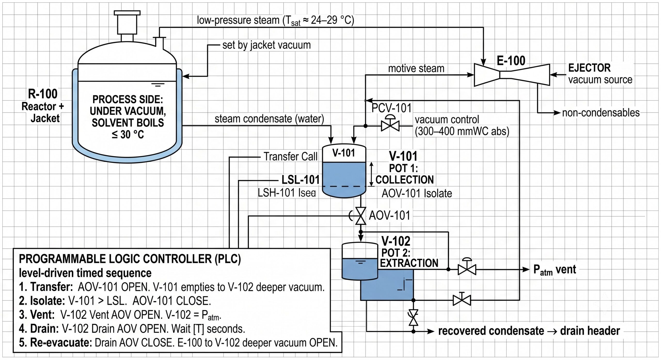
Pot 1, the collection pot. A vacuum-control valve holds Pot 1 in the 300–400 mmWC absolute band — at the same pressure as the jacket. Condensate flows out of the jacket into Pot 1 with no disturbance to the jacket vacuum, and therefore none to the reactor. That decoupling is the whole point of the design.
Transfer on high level. When Pot 1 reaches its high-level set point, Pot 2 — already pumped down to a deeper vacuum by the ejector — is opened to it. The pressure difference draws the condensate from Pot 1 across into Pot 2, until Pot 1 hits its low-low level and is isolated. The transfer is sequenced so that Pot 1’s pressure stays inside the 300–400 mmWC band throughout: the collection pot’s pressure swing is kept tight, so the reactor never feels it.
Drain on the other side. Once Pot 2 is isolated and holding the condensate, it is vented to atmosphere and gravity-drained to the condensate header. It then re-evacuates and waits for the next high-level call from Pot 1. The two pots act as a pressure airlock, ferrying condensate from deep vacuum out to atmosphere in steps, with no tall leg anywhere in the system. The ejector supplies the working vacuum and, usefully, carries away non-condensables continuously.
The whole sequence — pump down, connect, transfer, isolate, vent, drain, re-evacuate — was automated on level switches and the vacuum-control valve. After some tuning of the level set points and the valve timing, it ran cleanly and continuously, with the collection-pot pressure swing held tight enough that the reactor temperature stayed flat throughout recovery.
6. Performance and Closure
The numbers moved the way they had to. Yield came back to about 95% — the figure the lab had promised all along — and the batch cycle time fell from 36 hours back toward the 16-hour design basis. With the recovery step finally delivering its duty inside the temperature ceiling and the time window, the batch was profitable again: from roughly a $16,000 loss to a $16,000 gain every time the reactor turns over — a swing of about $32,000 per batch — with the shorter cycle restoring throughput on top of that.
What the project left behind was a set of principles that travel well beyond this one molecule:
Principles That Travel
- Heat transfer is usually what doesn’t scale. A step that is trivial in a flask can be the binding constraint in a reactor, because the heat-transfer area per unit volume falls as size grows. De-risk the heat-transfer duty before you trust a lab yield at plant scale.
- Choose the heating medium by the temperature ceiling, not by habit. For a hard thermal limit, a condensing medium under vacuum lets you set the maximum wall temperature by setting a pressure — and it delivers high flux across the small ΔT a fragile product forces on you. No sensible-heat medium does both.
- Deep-vacuum steam is voluminous. Size lines and equipment for the specific volume (tens of m³/kg) and keep the pressure drop low, or the isothermal jacket won’t be isothermal. Purge the non-condensables.
- Plan condensate removal before you celebrate the heat transfer. Back-up turns into back-pressure, and back-pressure walks the temperature up past the ceiling. A barometric leg to atmosphere needs about one atmosphere of water — roughly 10 m — which most plants do not have on an upper floor.
- When you cannot get the height, stage the pressure. A twin-pot lock-hopper moves liquid from vacuum to atmosphere in isolated steps and removes the need for a tall leg entirely.
- Decouple the subsystems. Hold the collection pot at the jacket’s own pressure so condensate handling never perturbs the reactor. The architecture should make crossing the temperature ceiling physically difficult, not merely unlikely.
Two turns decided this project, and both came from a senior who had seen the failure modes before — the choice of vacuum steam, and the twin-pot way around the height limit. Neither became a working plant on its own. Reading the pressure band off the steam tables, designing the pots and their sequence, automating the cycle and tuning the set points until the collection pressure held steady — that was the engineering, and it was where the result was actually won. Good plant problems tend to be solved this way: judgment from the people who have seen it before, execution from the people willing to size it, build it, and tune it.
A companion piece on sizing the jacketed agitated Nutsche filter for the −25 °C filtration step is in the works.
Engineering services
The same systematic approach that rescued this batch — read the physics, choose the medium by the constraint, engineer the supporting system, and tune it until it holds — is what Orissa Engineering brings to plants under pressure.
Process Troubleshooting & Scale-Up
Diagnosing why a proven lab or pilot route fails at plant scale — heat transfer, mass transfer, mixing, and cycle-time bottlenecks — and engineering the fix.
Commissioning Rescue
Stabilising stalled or under-performing units during commissioning, from control-philosophy reviews to hands-on cause analysis on the floor.
Equipment & System Design
Sizing and specifying jacketed reactors, vacuum and condensate systems, filtration, and recovery trains for heat-sensitive and demanding chemistries.
Technical Advisory
Lender’s engineer, owner’s engineer, and independent process due-diligence — an honest read on whether a process will make money at scale.
Have a process that works in the lab but not the plant?
The initial review costs nothing. Tell us what the batch is doing and we’ll tell you where to look.
Discuss a Project
Message sent successfully
Thank you for reaching out. We will review your project details and get back to you within 1 business day.
Discuss a project
Commissioning rescue · process troubleshooting · technical advisory